
Geometric Optics
In the first part of this lab, we will investigate the basic principles of ray optics, Snell's law and the Law of Reflection.
In the second part of this lab, we will study the application of these laws to lenses.Hoveroverthese!
- Optics Kit:
- Laser Apparatus
- Triangular Prism, plane mirror
- Graph Paper
- Large and mini laminated protractors
- Vernier Optics Lens Kit:
- Optical (and mechanical) Rail
- Lamp with various objects, including "4"
- Lenses:
- 10cm Converging Lens
- 20cm Converging Lens
- 15cm Diverging Lens
- Screen
- Rotatable blocking screen
- Record data in this Google Sheets data table
Ray Optics
There are two phenomena that occur when a light beam hits an interface between two different kinds of material: refraction and reflection.1
Refraction occurs when the light is transmitted into the new material, but at a different angle than it came in. Reflection occurs when the light reflects back into the material whence it came.
In both cases, we first draw a line perpendicular to the interface, which we call the normal. The basic angles we deal with in optics are the angles between a beam of light and the normal.
For reflections, the law of reflection states that the incoming angle (with respect to the normal) and the outgoing angle (w.r.t. normal) are the same. This is true regardless of the details of the reflection (whether you are going "inside" a material to "outside," vice-versa, or bouncing off a mirror).
For refractions, the angles are instead governed by Snell's law:
$$n_1\sin(\theta_1)=n_2\sin(\theta_2)$$Here, we label the two sides of the interface by \(1\) and \(2\) (with, usually, \(1\) being the side of the incoming beam, and \(2\) being the side of the refracted beam). The quantities \(\theta_1\) and \(\theta_2\) are then the angles (w.r.t. normal) of the light beam on the respective sides of the interface.
The quantities \(n_1\) and \(n_2\) are the indices of refraction of the materials on each side of the interface. The index of refraction is a property of a material which describes how fast light moves in a material (\(v\)) vs. in vacuum (\(c\)):
$$n=\frac{c}{v}$$Hence, \(n=1\) for vacuum, and approximately so for air. Otherwise (generally), \(n>1\).1
When a beam of light moves from an area of higher \(n\) to lower \(n\), depending on \(\theta_1\), it is possible that there is no \(\theta_2\) that will cause Snell's law to hold. Thus, no light can be refracted, and we have what is called total internal reflection.
A full formula for the intensity of the reflected vs. refracted beams are beyond the scope of this course (and, in fact, depends on the polarization of the light). Nevertheless, one basic principle that governs these powers can be understood.
The intensity of the beam is the power (energy per unit time) transmitted per unit area. Therefore, by conservation of energy, if no light is absorbed (which is a separate possible phenomena), the total incoming intensity has to equal the total outgoing intensity.2
Lenses
If a piece of refracting material is shaped appropriately, it will focus or defocus the light. If the light rays are focused to (approximately) a point, or defocused so they approximately look like they're coming from a single point, then we call that a lens.23
Suppose the rays come into the lens parallel, and consider the outgoing rays (extending them backward behind the lens as well). These rays will all meet at some point, known as the focal point.
The forward-displacement to the focal point is known as the focal length, \(f\). (This means that if the focal point is behind the lens, as occurs for a diverging lens, then the focal length is negative.)
In general, understanding how lenses make images requires a whole bunch of complicated geometry. With lens is thin, however, one can make an approximation4 that leads to the thin lens equation:
$$\frac{1}{d_o}+\frac{1}{d_i}=\frac{1}{f}$$Here, \(d_o\) is the distance to the object (always defined as positive) and \(d_i\) is the distance to the image (positive if the image is "forward" from the lens and real, negative if it is "behind" and virtual).
The image from the lens may be magnified (larger) or demagnified (smaller). The magnification is defined as the ratio of image size \(h_i\) to object size \(h_o\) (with a negative sign if the image is flipped vertically, calculated as a negative \(h_i\)):
$$m=\frac{h_i}{h_o}$$Some geometry (using similar triangles) also allows us to calculate the magnification in terms of the distances (with the same sign conventions as above):
$$m=-\frac{d_i}{d_o}$$The relationship of these quantities to visual size is a bit more complicated. How large something appears is dependent on its angular size (what fraction of our vision it occupies), not its actual size - hence why distant things look smaller. Whether you care about linear or angular magnification is dependent on what you are doing.
This lab has two separate apparatuses: the optics kit (Part I) and the lens kit (Part II). Each one will occupy half the lab benches; there are insufficient setups to fill the whole room with both.
Begin by performing the portion of the lab that corresponds to the setup at your bench. Halfway through the lab (or once you are done with your part and a group with the opposite setup is done with theirs), switch setups, and do the other part.
If you are waiting around to switch, play around with the equipment provided. What else do you observe? (There's plenty to see beyond what we actually measure in this lab, especially with the optics kit.) Write down if you notice anything significant!
Part IA: Basic Refraction
In this part, we are going to measure all of our angles by measuring distances. This will enable us to measure them with a reasonable degree of precision.
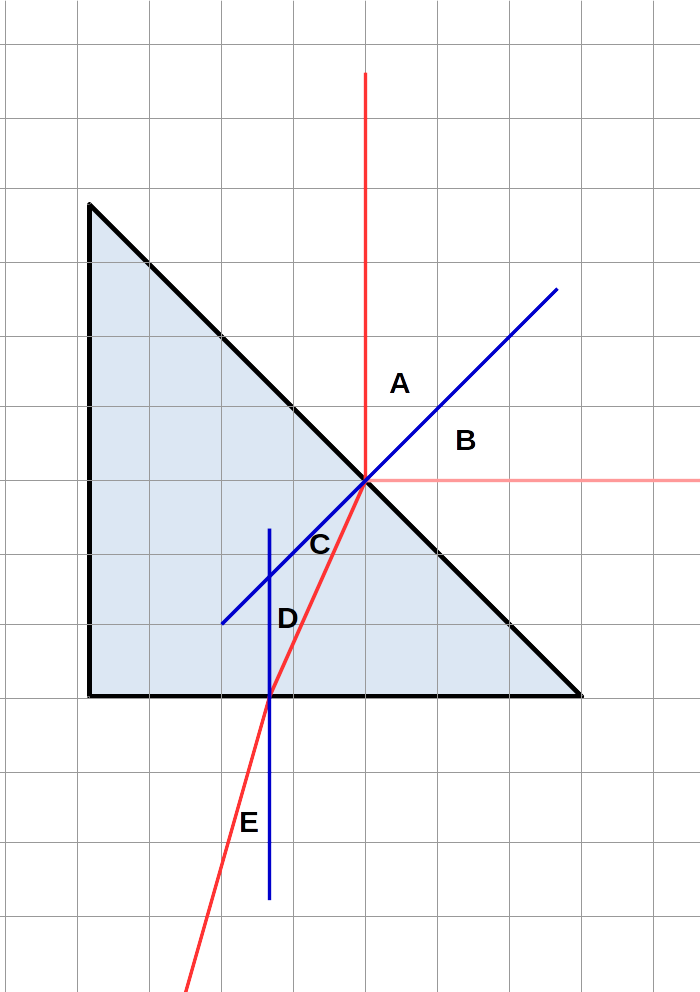
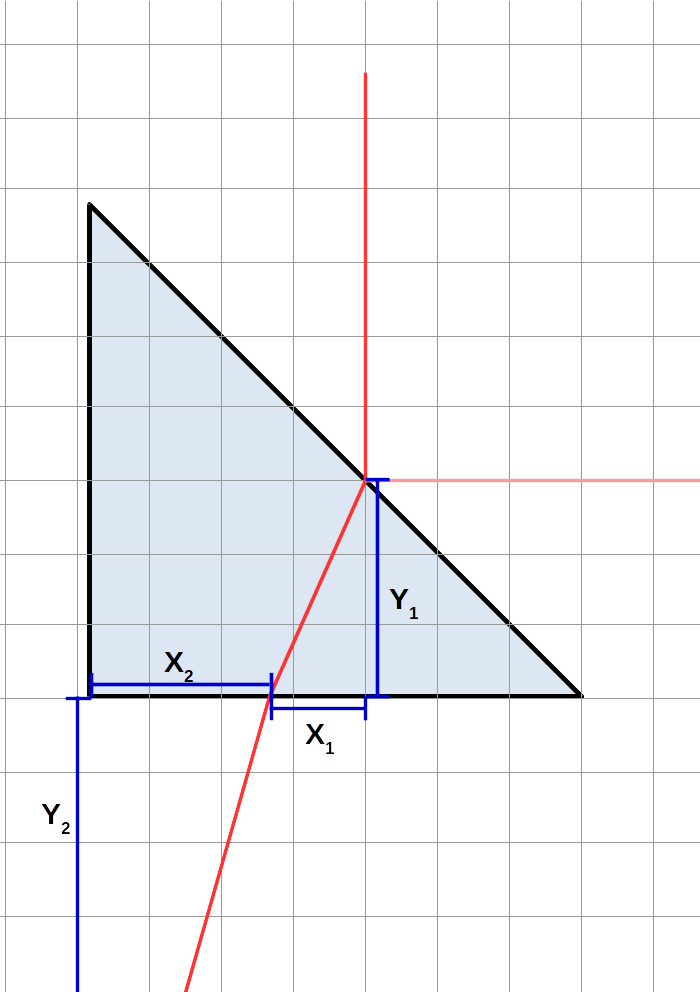
The angles and distances we will look at1 are shown in the following diagrams. Red lines are the laser beams; in the left diagram, blue lines are normals. (Note \(Y_2\) extends downwards to the location of the light beam at that x-coordinate.)
Take the \(45^\circ\) triangular prism, your laser, and one sheet of graph paper. Plug in your laser, and set it to output one beam (middle setting on the switch). Press the button and make sure it shines a beam.2
Place the triangular prism on the graph paper such that one of the shorter edges aligns with one of the grid lines. Slide sideways until the \(45^\circ\)-angle-corner of that side is on a grid line intersection. (See diagram below if these instructions are confusing.)
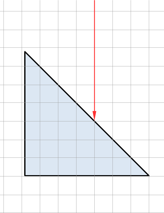
Now, take the laser and shine it on the prism perpendicularly to the edge you lined up, from the hypotenuse side. Line the laser up so that its beam travels along the gridline which has three boxes inside the prism.
Schematically, your setup should be illustrated by the following figure (the location of the left edge of the prism may vary):
Now, measure the distances \(X_1\), \(Y_1\), \(X_2\), and \(Y_2\). Measure as precisely as you can here, ideally to sub-millimeter precision - you'll get better results that way. Estimate uncertainties.
Part IB: External Reflection
Set aside the graph paper, and take the giant laminated protractor paper from the kit. In this part, we will measure angles directly.
Begin by lining up the hypotenuse of the trianglular prism with the 90° line on the protractor (such that the normal is along the 0° axis).
Put the laser off at some angle (less than 90 degrees from zero), and point it towards the center of the protractor. Measure both the angles with respect to the normal of both the incoming and reflected outgoing beam using the protractor. Estimate uncertainties.
Also take note of the relative intensity of the reflected beam compared to the incident beam.
Take out the mirror from your kit. Replace the prism with the mirror (laser in the same place, mirror along the 90° line).
Take note of the reflected intensity (compared to the incident intensity) for this component. (Think: why a difference?)
Part IC: Total Internal Reflection
In this part, we will again measure angles; however, they will be determined with significantly less precision than the last part.3
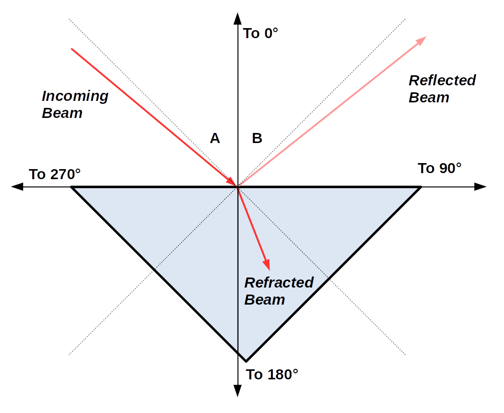
Place your triangular prism on the mini-protractor so that the hypotenuse is on the 90° line, so the right angle points towards 0°. Shine the laser on the prism in the following way:
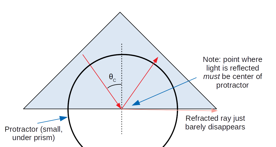
Rotate the laser until you reach the point where the outgoing refracted beam just disappears (by "folding into" the hypotenuse of the triangle). The angle on your protractor (if the laser is still pointed at the center of it!) is now the critical angle.
Adjust your positions until you feel you've got the best measurement of critical angle you can get, and record that value. Estimate its uncertainty (however precise you think you were able to get).
Now, let's make some qualitative observations of intensity. Rotate your prism so it's just outside the angle at which total internal reflection happens (so that you have a refracted beam that is almost gone).
Now, wiggle it slightly. How do the incident, internally reflected, and refracted beams vary in intensity, if at all, as you approach the critical angle (from the direction where the refracted beam appears)? (This is most visible when you're really close to the critical angle.)
Part II: Lenses (Setup)
Ensure that your optical track is set up correctly: the rail has location markers on it. The numbers should be on the top and facing you, so you can read them. If not, fix this.
Part IIA: Converging Lenses
First, grab the lamp, and place it at one end of the optical track. Ensure that the light is directed to shine on the rest of the track (without anything in the way of the "window" on the lamp). Select the number four ("4") as the object.
Then, select a 10cm converging lens, and place it in the middle of the optical track.
Similarly, place the screen on the other side of the lens. Move the lamp and the screen until they are some distance greater than 40cm apart from each other (say, ~50cm - not too far, or the light won't reach well).
Now, we will only move around the lens on the optical track. Shift it around until you see a focused "4" on the screen.
We will now take our first set of measurements. Measure the distance from the object "4" to the lens holder, then from the lens holder to the screen. (You can do this by looking at the optical track, which has tick marks on it.)
Then, take height measurements. Take a distance you can measure on both the object and image (the "4" has plenty of "features" to look at!), and measure that distance on both. Record these as \(h_o\) and \(h_i\) (again, with appropriate signs if needed: \(h_o\) is always positive, but is \(h_i\) positive or negative here?).
If you slide the lens around, you should find another place where the image focuses. Repeat the measurements you did for the previous position with this new focal point.
Part IIB: Diverging Lenses
Replace the 10cm converging lens with a 15cm diverging lens.
Shift it back and forth. Does it make a focused image on the screen at any point? Take note of this.
Now, take the 15cm diverging lens off of the track and look at the lamp.
Make observations about the orientation and (angular) size of the image of the "4" that you (should) observe by looking through the lens, in accordance with the questions on the data sheet.
Warning: Excel/Sheets/etc.'s trig functions assume inputs of radians, and the inverse trig functions output angles in radians. Pay attention to this when doing calculations involving trigonometric functions.
Part IA: Refraction
First, calculate angles \(C\), \(D\), and \(E\). For simplicity, here are the formulas for them (although you should verify that they are true):
$$C=A-D$$ $$D=\tan^{-1}\left(X_1/Y_1\right)$$ $$E=\tan^{-1}\left(X_2/Y_2\right)$$Then, calculate the sines of these angles (and \(A\)). Keep in mind (for both of these calculations) the warning above.
Note that, for both of these steps, we did the uncertainty propagation for you (because propagating uncertainty through trigonometric formulas is somewhat messy and uses specialized formulas that require calculus to motivate).
Then, using those sines, calculate the index of refraction, assuming \(n_\text{air}=1\), twice, once at each boundary (i.e., once using angles A and C, and once using angles D and E).
Finally, answer the questions on the data sheet about whether these agree with the expected value for \(n\).
Part IB: External Reflection
Answer the questions about whether your results agree/make sense.
Part IC: Total Internal Reflection
Calculate the sine of the critical angle (as above, keep in mind the warning, and the trig error propagation is done for you).
From this, calculate index of refraction, and propagate uncertainty.
Then, answer the questions about whether your results agree/make sense.
Part IIA: Converging Lenses
For each focusing point:
- Calculate the magnifications using the distances \(d_o\) and \(d_i\). Propagate uncertainties.
- Calculate the magnifications using the heights \(h_o\) and \(h_i\). Propagate uncertainties.
- Answer whether they agree (including signs!).
- Calculate the focal length using the thin lens equation. Propagate uncertainties. (The extra boxes should help you with that.)
- Answer whether your focal length agrees with expectation.
Part IIB: Diverging Lenses
Answer all questions on the data table. Then, draw a ray-tracing diagram that illustrates the magnification you observe.
Your TA will ask you to discuss some of the following topics (they will tell you which ones):
- Random Errors: Suppose you had some random error in \(X_1\) or \(Y_1\). Would this error have a same-direction or opposite-direction impact on angles \(C\) and \(D\)? A same-direction or opposite-direction impact on your two measurements of \(n\) in part IA? Suppose we got a measurement of \(n\) by averaging the two measurements we got in this part. Would you consider this feature of our errors to be a good thing or a bad thing from the perspective of getting an accurate measurement of \(n\), and why?
- Alternative Lens Configuration Choices:
- Why was it important that we placed the screen and the object at least 40cm apart in part IIA? What is special about 40cm, specifically? (Hint: you'll need to figure out how to relate the distance between screen and object to other parameters of the problem, and ultimately to the thin lens equation.)
- Suppose we had used a 2cm converging lens instead of a 10cm converging lens in part IIA while keeping the screen-to-object distance the same. Would the first point at which the image focuses (as we move the 2cm lens from the object towards the screen) be closer to or farther from the object than it was for the 5cm lens? Why? (In other words: would the smallest value for \(d_o\), with the same object-to-screen distance, be smaller or larger when \(f\) is reduced from 10cm to 2cm?) Be careful: both \(d_o\) and \(d_i\) are changing as we move the lens!
- If we had put the lamp and object really far away, what would be the distance between the (5cm converging) lens and the image? What would the magnification be? What would the orientation be (upright or inverted)? Would the image be real or virtual? (Hint: there's both a mathematical and physical way to understand this.)
- Alternative Methodology for Total Internal Reflection: How could we perform part III of this experiment by measuring only distances? (There are multiple potential answers here; come up with a set of measurements you think are plausible to perform, physically speaking, and a formula relating them to your conclusion. Show your work.)
- Radio Waves: The Earth's ionosphere has an index of refraction less than 1 (due to it being a plasma). Draw what a radio wave passing from the Earth's atmosphere (with \(n=1\)) into the ionosphere above might look like, based on Snell's law, for a large angle w.r.t. the relevant normal. (Hint: it's going from an area of larger index of refraction to one of smaller index of refraction... what can happen in such a case?) How might this aid long-distance radio transmission?
Hovering over these bubbles will make a footnote pop up. Gray footnotes are citations and links to outside references.
Blue footnotes are discussions of general physics material that would break up the flow of explanation to include directly. These can be important subtleties, advanced material, historical asides, hints for questions, etc.
Yellow footnotes are details about experimental procedure or analysis. These can be reminders about how to use equipment, explanations of how to get good results, troubleshooting tips, or clarifications on details of frequent confusion.
For a review of the basic principles of reflection and refraction, see Chapter 32 of Giancoli or Chapter 38 of Katz.
For a review of lenses (and especially thin lenses), see Chapter 33 of Giancoli or Chapter 38 of Katz.
This is a result of the fact that nothing can move faster than light in a vacuum, including light in a material. However, there are some subtleties (involving the difference between phase velocity and group velocity) which means that one can have \(n<1\) (or even, in some fancy cases, negative!), including the Earth's ionosphere, which enables radio waves (e.g., see this).
Slightly more precisely, this only holds if the beams don't change width (so there's no focusing/defocusing effects). A more correct statement is: the total intensity times area, added over all beams, is the same coming in as going out, unless there is a significant degree of absorption in your material.
To meet at exactly a point, the lens has to be a parabola. However, one often approximately works with a circle, which is good enough. The extra "problems" that arise with a circular lens are known as spherical aberration.
The approximation that goes into a lens being "thin" is that the light spends approximately no time in the lens, so we can ignore the effect that happens "in" the lens. That means that the net effect of the lens is just a change in angle, not a displacement of any kind.
Angle B (the reflected ray) will be examined in Part II, but the rest of them will be measured in this part.
Do this without shining it in someone's eyes, please - leave it flat on the table.
The difficulty of measuring the angles in this part will illustrate why we measured distances and not angles in part I. Unfortunately, there is not a way to perform a similar measurement here that is both computationally and physically easy (that we have found).
You may notice I didn't mention a displacement of the lamp. The lamp isn't displaced, but it doesn't matter: the light is supposed to be "from infinitely far away" anyway, so the exact position doesn't matter.