Capacitors
In this lab, we will be measuring the capacitance of a "fixed-capacitance" capacitor using a variable capacitance capacitor both in series and in parallel.Hoveroverthese!
- 2 Capacitors: 1 Fixed, 1 Variable
- 1 Voltmeter
- 1 Power Supply
- 1 Double-pole double-throw (DPDT) Switch
- 9 banana cables, 2 (or more) alligator clips
- Record data in this Google Sheets data table
Capacitor Basics
Suppose one has two conductive surfaces, one with charge \(Q\) and the other with charge \(-Q\). These conductive surfaces will have a voltage \(V\) between them, which is proportional to the charge \(Q\) with a constant of proportionality that depends on the shape and location of the surfaces.
This constant of proportionality, known as the capacitance \(C\), is defined by:
$$Q=CV\label{Cdef}$$A common simple capacitor setup is a parallel plate capacitor, which consists of two conductive plates of area \(A\) separated by a distance \(d\) with some insulating material in between. With the assumption that \(A\gg d^2\),1 this is (approximately) directly computable:2
$$C=\frac{\epsilon A}{d}\label{Cplates}$$The material in between is usually chosen to enhance the capacitance; such a material is known as a dielectric. Then, \(\epsilon\) is a constant known as the permittivity of that material. If there is a vacuum (or, approximately, air) in between, then \(\epsilon=\epsilon_0\) is the permittivity of free space.
Capacitors In Circuits
In general, capacitors in circuits are governed by two main rules:1
- Kirchoff's voltage law: Any two "paths" through a circuit have the same sum of voltage changes across each component.
- Corollary: components wired in parallel have the same voltage drop across them.
- Corollary: components wired in series to a power supply have their voltages add to the voltage of the power supply.
- Conservation of charge: If a portion of wire is not connected to a power supply, the sum of charges on plates attached to that wire remains fixed over time.
In this lab, we will first put two capacitors in series, one of variable capacitance and one of fixed capacitance. They will begin totally discharged, and then (with the flip of a switch) we will charge them to some total voltage \(V_0\). In this process, the final charge on both capacitors are equal.
For a variety of total voltages \(V_0\), we will measure the voltage across each capacitor. We can compute the charge across the variable capacitor, and use this to deduce the charge across the fixed capacitor. From the charge and voltage measurements for the fixed capacitor, we can deduce the capacitance (which can be compared with the listed value).
Then, we will wire the capacitors in parallel. We will begin by charging the fixed capacitor up to a known voltage \(V_0\). With a flip of a switch, we will disconnect the power supply and connect the variable capacitor in parallel with the first capacitor. We will then measure this final voltage, \(V_{||}\).
Since the charge across the fixed capacitor initially is the same as the total charge across both at the end, we can relate the capacitance \(C_1\) to the final "parallel capacitance" \(C_{||}\):
$$Q_\text{tot}=V_0C_1=V_{||}C_{||}\label{Qtot}$$We know on theoretical grounds what we expect for \(C_{||}\) in terms of the individual capacitances \(C_1\) and \(C_2\):
$$C_{||}=C_1+C_2\label{Cpara}$$RC Circuits
In real circuits, capacitors do not instantly equilibrate - the charges take time to move. The length of time it takes for it to reach equilibrium depends on the resistance of the other components - how much they resist the flow of charges (i.e., current) through them. The larger the resistance, the slower the charges move, so the longer it takes to reach equilibrium.
The exact behavior when we include the resistance is a subject for later in the course; here's a one-sentence overview. With a resistance (with SI units of ohms, denoted by Ω) of \(R\), the time it takes to get "close" to equilibrium3 (or time constant) is denoted by:
$$\tau=RC$$An "ideal" wire should have zero resistance - it would be a perfect conductor, so charges move around instantaneously. (Real wires, combined with realistic contact resistances, can add up to ~Ω-scale resistances across the lengths of wire used in this lab.)
On the other hand, an "ideal" voltmeter should have infinite resistance, so that charges cannot "leak" through it. (A real voltmeter will tend to have ~MΩ-scale resistances.)
Part I: Capacitors in Series
First, take the fixed capacitor (i.e., the object without any dials or anything on it). It should have a listed capacitance (of 5 or 6μF) and corresponding uncertainty; find and record this number as your theoretical \(C_1\) [for Part I; the corresponding boxes in Part II should fill automatically].
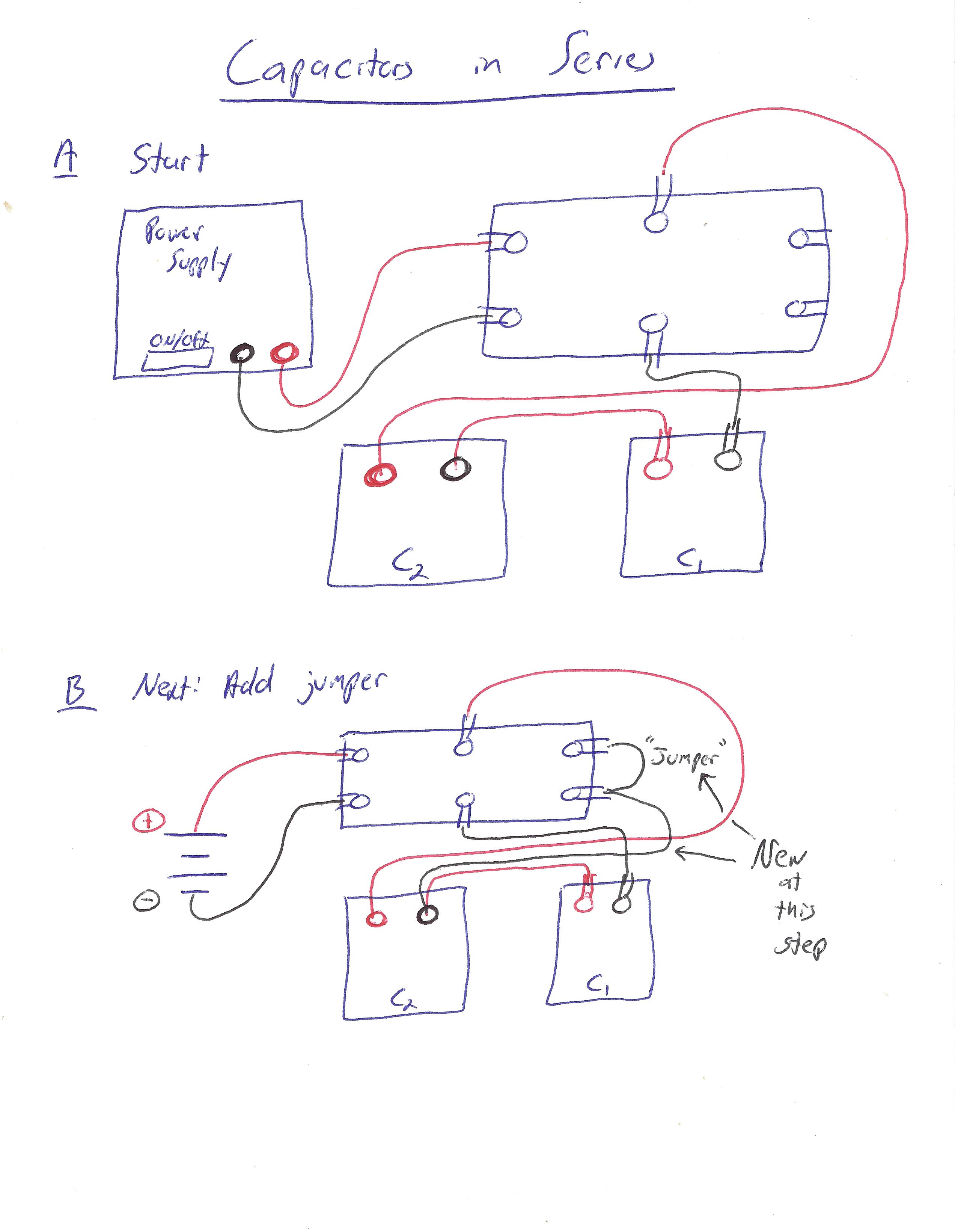
Then, wire the capacitors in series, according to the following diagrams:


Click here for wire-by-wire instructions.
(For simplicity of using these instructions, orient the switch so that it flips left to right.)
We assume you are starting with no wires connected:
- Wire a red wire from the red terminal on the power supply to the back left terminal of the switch.
- Wire a red wire from the back middle terminal on the switch to the red terminal on the variable capacitor \(C_2\).
- Wire any wire (but preferably red) from the black terminal on the variable capacitor \(C_2\) to one of the terminals on the fixed capacitor \(C_1\).
- Wire a black wire from the other terminal on the fixed capacitor \(C_1\) to the front middle terminal on the switch.
- Wire a black wire from the front left terminal on the switch to the black terminal on the power supply.
Now, when the switch is in the left position, you should have a complete loop starting at the red terminal of the power supply, passing through \(C_2\) and \(C_1\), then ending at the negative terminal of the power supply.
Next, we want to set it up so that the right position on the switch discharges both capacitors. Note since the power supply is connected only to the left side of the switch, the power supply will be disconnected in this position.
- Wire either color wire from the back right terminal on the switch to the front right terminal.
- Wire either color wire from either of the rightmost terminals to the black terminal on the variable capacitor \(C_2\).
You should now have the capacitors fully discharge when the switch is in the right position.
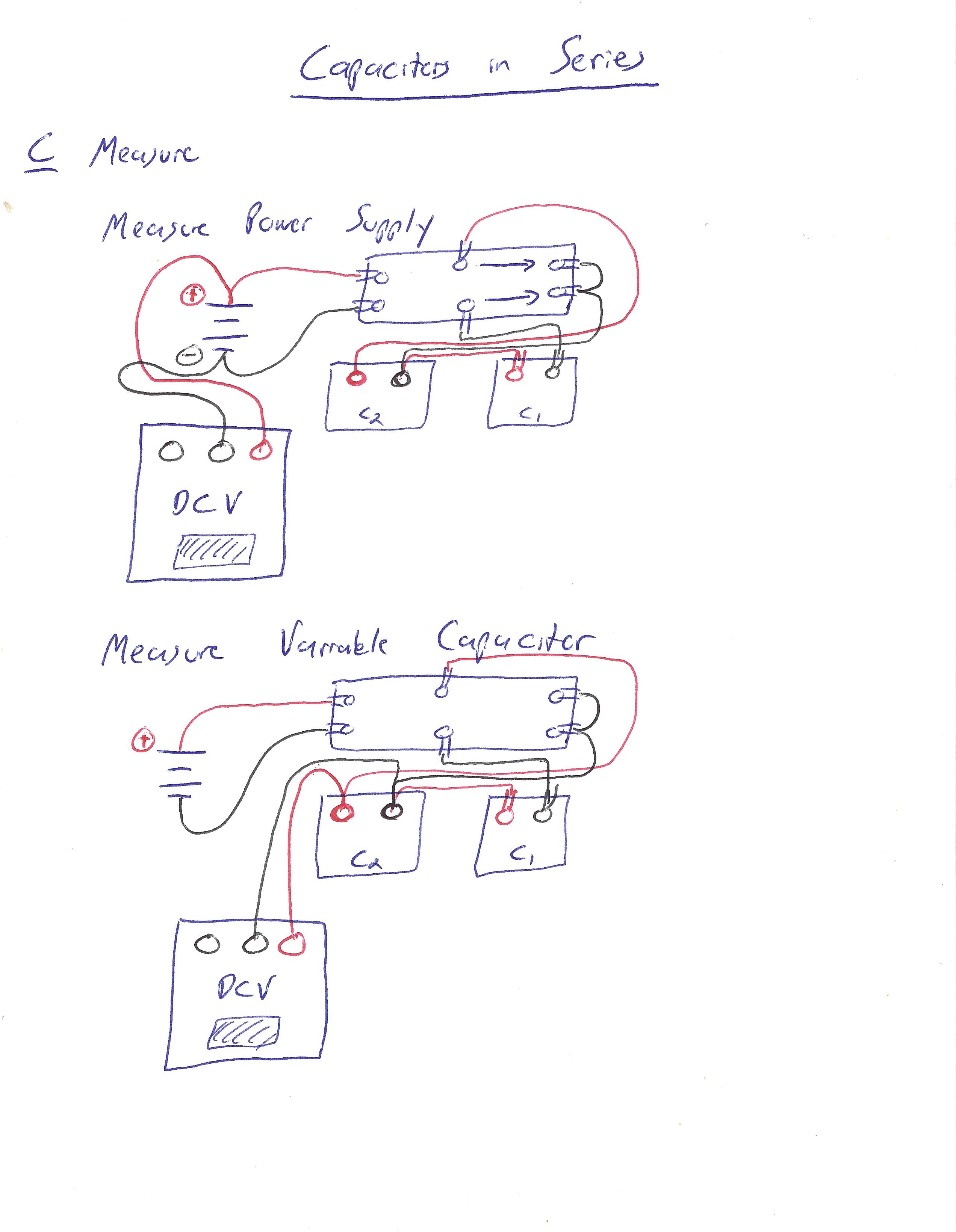
There is still the multimeter to connect, but you will be moving it around, since we want voltages across both components here.
For simplicity, for the rest of this part, we use the convention that "left" on the switch means "in the state where the capacitors are charged", and "right" means "in the state where the capacitors are discharged." (This is consistent with the orientation in the above pictures and wiring instructions.)
Discharge your capacitors (i.e., put the switch in the right position), set your voltmeter to a 20V maximum, and set your power supply to output 3V. Then, using the voltmeter, measure and record the actual voltage across your power supply.1 2This should remain constant throughout this experiment (although it won't actually change your capacitance results if you vary it). Remember to disconnect the voltmeter from the power supply after this measurement.
Now: set the variable capacitor \(C_2\) to 10μF, and record this value. Wire your voltmeter so it is measuring across the variable capacitor \(C_2\) (although it should be reading zero at present, since the capacitor is discharged).
Now, let's check that we have hooked it up correctly. Flip your switch to the left and look at your voltmeter: it should jump up to some (positive) voltage, then slowly start to drop. Then, flip it back to the right; your number should drop to zero. (If it doesn't change as you expect, check your wiring (twice), then consult your TA.)
Alright, now to actually take the measurement. We want to record the number the voltmeter measures after the "jump up," but before the "slow drop"; in this part, this should be the maximum value the voltmeter displays. Flip the switch and record this as the voltage across the variable capacitor, \(V_2\). Then, discharge the capacitors by flipping the switch right again.
Now, move the voltmeter so that now it measures across the fixed capacitor \(C_1\) instead of the variable capacitor \(C_2\). As you did when measuring \(V_2\), flip the switch left and record the "end-of-jump" voltage that appears, this time as \(V_1\). Then, flip the switch right and let it discharge again.
Repeat this process (measuring \(V_1\) and \(V_2\)) for different values of \(C_2\), up to 10μF in increments of 2μF.
Part II: Capacitors in Parallel
Now, we want to wire our circuit so that one direction on our switch connects \(C_1\) to the power supply, and the other direction connects it to \(C_2\).
We also want to be able to discharge capacitor \(C_2\) between trials, so we'll set up our switch to do that, too, for convenience. (We could also "short out" the capacitor by touching a wire to each terminal of it, but there is no need to do so, since our switch can do that job.)
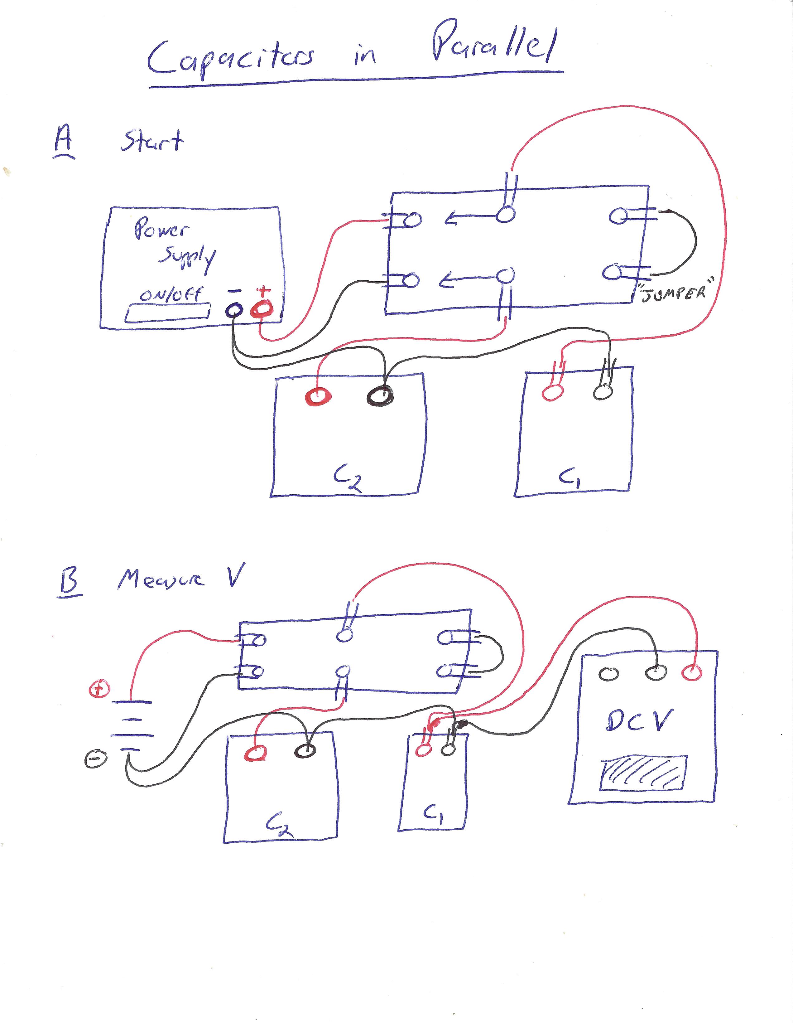
Accordingly, wire up your circuit according to the following diagrams:

Click here for wire-by-wire instructions.
(For simplicity of using these instructions, orient the switch so that it flips left to right.)
We assume you are starting with no wires connected:
- Wire a red wire from the red terminal on the power supply to the back left terminal on the switch.
- Wire a black wire from the black terminal on the power supply to the front left terminal on the switch.
- Wire a red wire from one terminal on the fixed capacitor \(C_1\) (using an alligator clip) to the back middle terminal on the switch.
- Wire a black wire from the other terminal on the fixed capacitor \(C_1\) to the front left terminal on the switch.
Now, if the switch is flipped to the left side, you should have a complete "loop" from the positive end of the power supply, through \(C_1\), and back to the negative end of the power supply.
- Wire a black wire from the black terminal on the variable capacitor \(C_2\) to the front left terminal on the switch.
- Wire a red wire from the red terminal on the variable capacitor \(C_2\) to the front middle terminal on the switch.
This should make a closed loop from one end of \(C_2\) to the other when the switch is in the left position, causing \(C_2\) to discharge in this position.
- Connect a short wire (red or black is fine) from the back right terminal on the switch to the front right terminal on the switch.
Now, when the switch is in the right position, the only "loop" should be the one involving the two capacitors, where the "positive" (red-wire) terminals are connected to each other and the "negative" (black wire) terminals are as well.
- Connect a red wire from the red (+) terminal on the voltmeter to the positive (red-wire) terminal on the fixed capacitor \(C_1\).
- Connect a black wire from the black (-) terminal on the voltmeter to the negative (black-wire) terminal on the fixed capacitor \(C_1\).
The voltmeter should now be measuring the voltage across capacitor \(C_1\).
For this part, we use the convention that "left" on the switch means "in the state where we charge the capacitor \(C_1\) and discharge \(C_2\)", and "right" means "disconnected from the power supply, with the capacitors connected together." (Again, this is consistent with the above pictures/instructions.)
Flip your switch to the left position, and set your power supply to output 3V. Turn on your voltmeter with a 20V max; it should be reading approximately 3V. Record this voltage as \(V_0\).
Now, set \(C_2\) to 10μF and flip your switch to the right position. Now, you should record a sudden drop in voltage (as \(C_2\) dischrages into \(C_1\)), followed by a slow decline to zero. (Again, if you don't see this, consult your TA.) Flip it back left to re-charge \(C_2\) and discharge \(C_1\).
The number we are going to want to record (as \(V_{||}\)) is the number that appears at the end of the sudden drop, but before it changes from the slow decline. Unfortunately, unlike the previous part, there isn't an easy criteria here (like the "maximum value"), but it should be pretty easy to judge by eye.3
Now: flip the switch back right and record \(V_{||}\) as described above.
Part III: RC Circuits
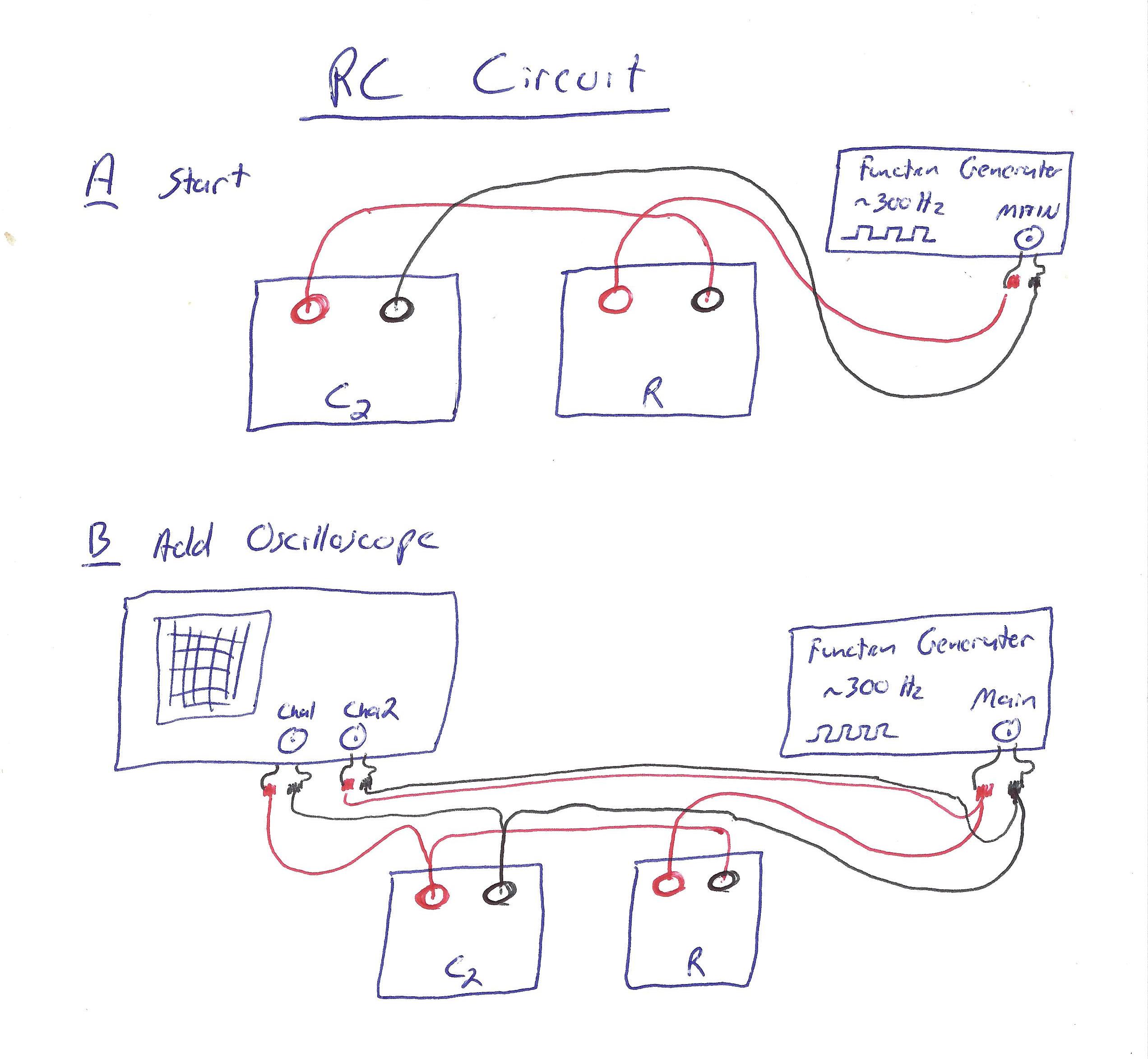
Wire up an RC circuit, driven by the function generator, as follows:

Click here for wire-by-wire instructions.
We assume you are starting with no wires connected:
- Wire a red wire from the red terminal on the function generator to the red terminal on the resistor.
- Wire a red wire from the black terminal on the resistor to the red terminal on the variable capacitor.
- Wire a black wire from the black terminal on the capacitor to the black terminal on the function generator.
Now, you should have a complete "loop" from the red terminal on the function generator, through the resistor, then through the capacitor, and finally back to the black terminal on the function generator.
- Wire a red wire from the red terminal on the function generator to the red terminal on CH2 of the oscilloscope.
- Wire a black wire from the black terminal on the function generator to the black terminal on CH2 of the oscilloscope.
CH2 of your oscilloscope should now be measuring the voltage across the function generator.
- Wire a red wire from the red terminal on the variable capacitor to the red terminal on CH1 of the oscilloscope.
- Wire a black wire from the black terminal on the variable capacitor to the black terminal on CH1 of the oscilloscope.
CH1 of your oscilloscope should now be measuring the voltage across your capacitor.
With this setup, the oscilloscope displays both the "input" voltage (from the function generator) and the "resulting" voltage on the capacitor.
Set your resistance to 1kΩ and your capacitance to 0.1μF. Then, set your function generator to output a ~300Hz square wave.2
Special Note in Spring 2024 2025: In Room A-119 A-130, set your resistance to 30Ω and your capacitance to 3.0μF. Follow the same procedure otherwise.
Set up your oscilloscope so you can view the square wave and capacitor voltage nicely (on the DUAL setting).3 Adjust the two waves' vertical positions so that their centers align. Having the VOLTS/DIV be the same for both is advisable for the sake of intuiting what is going on.
What you observe should highlight how the capacitor repeatedly charges and discharges and the function generator changes its input voltage.4
Now: vary both the capacitance and resistance, and record your observations. In particular: what happens to the "rate of charging" as you vary the resistance? The capacitance?
With this determined, your measurements are taken; turn stuff off and unplug all your banana wires for the next class.
Part I: Capacitors in Series
For each data point, calculate \(Q_2\), the voltage on the variable capacitor, and propagate uncertainty. Note this is also \(Q_1\).
Make a plot of \(Q_1\) vs. \(V_1\). If you orient your axes appropriately, the slope of this plot should be \(C_1\).
Based on your results, answer the question about compatibility with expectation.
Also add together \(V_1+V_2\), propagating uncertainties. Comment on the outcome in your report.
Part II: Capacitors in Parallel
Calculate the theoretical value of \(C_{||}\) using equation \eqref{Cpara}, using the theoretical value of \(C_1\), and propagate uncertainties.
Then, compute the experimental value using equation \eqref{Qtot} (and the same value of \(C_1\)), and propagate uncertainties.
Based on your results, answer the question about compatibility with expectation.
Your TA will ask you to discuss some of the following points (they will tell you which ones):
- Circuit Diagrams: For each of the first two parts, draw a circuit diagram illustrating the schematic setup of the circuit.4 A few notes to help you out:
- For the first part, just draw the voltmeter measuring across the variable capacitor \(C_2\) [so you don't end up drawing a bunch of extra circuit diagrams with the voltmeter moved for this part.]
- Note that there are two ways to represent the switch: you can use an appropriate representation of a DPDT switch (i.e., a switch with six inputs set up in the way we did here), or you can draw two circuit diagrams per part (one for each connection setting on the switch, excluding the disconnected "middle position").
- If you choose to use a DPDT switch in your circuit diagram, here's a short explanation of the symbol (in terms of the diagramming software linked in the above footnote):
- The DPDT switch symbol has two connections on the left (call the top one A and the bottom one B), and two connections on the right (call them 1234 from top to bottom).
- A/B are the "middle terminals" on our switch, and 1234 are the "corner terminals."
- If our switch is in the left position, this corresponds to connecting A to 1 and B to 3 in the diagram. If our switch is in the right position, this corresponds to connecting A to 2 and B to 4 in the diagram. [Or, equivalently, you can swap left and right in that description, since the switch is symmetric.]
- Derivation of \(C_{||}\): Explain/derive formula \eqref{Cpara}, taking \(C_{||}\) to be defined as in equation \eqref{Qtot}.
- Derivation of \(C_\text{series}\): There is a formula somewhat analogous to \eqref{Cpara} for capacitors in series: if you take the setup described in part I, you relate the charge \(Q\) on either capacitor5 to the voltage of the power supply \(V\) and find that \(Q=C_\text{series}V\) for some \(C_\text{series}\) that can be expressed in terms of \(C_1\) and \(C_2\). State what this formula is, and prove that it holds.
- Derivation of Capacitance Formula: Derive formula \eqref{Cplates}, using electrostatics. You may assume the plates are in vacuum, so \(\epsilon=\epsilon_0\).
- RC Circuits: Do not just say "the formula \(\tau=RC\) says so" for this part; the point is to justify the formula, not to use it.
- Explain (qualitatively) why it is reasonable for the "time to equilibrium" to increase with resistance.
- Explain (qualitatively) why it is reasonable for the "time to equilibrium" to increase with capacitance.
- Explain (quantitatively, using dimensional analysis) why \(\tau=RC\) is the "only option" for the timescale in an RC circuit. (You may use the fact that 1Ω=1s/F, as well as assuming that the only "inputs" are the resistance \(R\), the capacitance \(C\), and the input voltage \(V_0\), in this explanation.)
- RC Effects in Parts I & II: In the first two parts of this experiment, we observe that when we flip the switch, the voltage first very quickly changes to one value, then slowly changes after that. Let's examine how to explain this.
- Suppose the wire has a 10Ω resistance (which is almost certainly an overestimate) and the voltmeter has a 1MΩ resistance (1Ω=1s/F). Given that our capacitances are of order ~10μF, compute the time constant for each resistance: this is essentially the time it takes for current to "go through" that component. From these timescales, consider: of the two processes described above (the quick change in voltage and the slow change in voltage), which process is controlled by each component's resistance?
- On very long timescales (minutes-to-hours), the voltmeter can essentially be considered as another wire - current can pass through it given enough time. Based on this, if we were to leave the capacitors in Part I in the left (capacitors charged) position for a very long time, what voltages would you observe on each capacitor? What if we left the capacitors in Part II in the right (capacitors connected together) position for a very long time?
Hovering over these bubbles will make a footnote pop up. Gray footnotes are citations and links to outside references.
Blue footnotes are discussions of general physics material that would break up the flow of explanation to include directly. These can be important subtleties, advanced material, historical asides, hints for questions, etc.
Yellow footnotes are details about experimental procedure or analysis. These can be reminders about how to use equipment, explanations of how to get good results, troubleshooting tips, or clarifications on details of frequent confusion.
The requirement \(A\gg d^2\) specifies that we can approximate it as a constant electric field in between - i.e., we can neglect the "fringe effects" at the edge of our plates.
The formula is qualitatively similar for a much wider variety of capacitors, but the details (like an overall coefficient) often change subtly.
Somewhat more accurately, this is the time it takes for the difference between the voltage and the equilibrium voltage to reduce by ~63%. Even more accurately, the difference in voltage is proportional to \(\exp(-t/\tau)\) for that constant \(\tau\).
More accurately, the capacitor is going between voltages \(V_0\) and \(-V_0\), not \(V_0\) and \(0\), so it repeatedly charges in one direction, then the opposite direction. This doesn't change the "time to equilibrium," though.
This is also the charge drawn from the power supply, which is what makes this "effective capacitance" a useful quantity in larger circuits. (E.g., it's the \(C\) that would go into the calculation of \(\tau\) for an RC circuit with this pair of capacitors and some resistance.)
Note: although we are not providing specific wiring instructions, you should know how to do this (and later, similarly, measuring voltages across your capacitors). Simply take a red wire from the red (+) terminal of the voltmeter and a black wire from the black (-) terminal of the voltmeter and put them into your circuit in appropriate places: red wire on the "high" side (closer to the red terminal on the power supply) of the component you want to measure across, black wire on the "low" side of that same component.
Yellow, "CE" brand voltmeters and the black & grey voltmeters made by our shop have only two connections: red and black.
With an Innova brand multimeter use the rightmost (red) connector for red and the center (black) connector for black. Set the multimeter to dcV mode (at 1 o'clock).
This voltage (or something pretty close to it) should be consistent from flip to flip, so if you're not sure which number to take, do multiple trials and take the largest voltage that shows up consistently.
You could draw this by hand, or you could make a nice diagram in a nice editor.
For more on capacitors, see Chapter 24 in Giancoli and Chapter 27 in Katz.
For a review of how to do this on different function generators, see our Notes on the Function Generators.
For a review of how to use the oscilloscope to do this, see our Notes on the Oscilloscope, or look back at the Oscilloscope Lab.