
Oscilloscopes
The oscilloscope is the most complicated piece of equipment we use in our lab, and any reasonably-concise explanation will leave out some details. As such, it is important that you make the most of the lab dedicated to understanding its use.
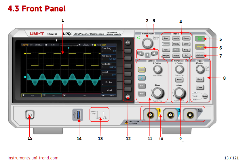
In short, an oscilloscope makes a plot of voltage versus time, where the voltage is detected as an input signal (CH1 or CH2).
The interface of the oscilloscope is filled with options, many of which are designed to edit how this plot is displayed: the position of the plot on the screen, the x and y axis scales, etc.
The basic picture you should have is the following: a dot moves across the screen, from left to right. As it does so, it moves up when the voltage is high and down when the voltage is low. If the dot moves quickly enough (which it will, for our signals of interest), it appears to turn into a line.
The key subtlety behind the oscilloscope is triggering. Ideally, if we input a periodic signal (say, a sine wave), then we want to see that signal, traced out again and again, so that we see a stable "picture" on our screen.
This only works if each time the signal appears, looks the same. For a sine wave, this is true only if we start our plot at the same point on the signal every time we start a new sweep across the screen.
This is essentially the role of the trigger: it says "start scanning when the voltage is at this point" (and moving [up/down]). This ensures we start at the same point on the sine wave (or whatever other signal) each time.
A final thing worth noting is that the oscilloscope actually has two inputs. It can plot either one of these inputs or both simultaneously, and can trigger off of either one. (It also has a third input - EXT - which can only serve as a trigger, but we won't use that.)
There is a lot more complexity to this device, but abstractly, those are the basic principles on which it operates.

Here is a data sheet for this series oscilloscope from the manufacturer, Rigol.
Here is a user manual for this series oscilloscope from the manufacturer, Tektronix.
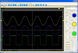
A digital oscilloscope uses an analog-to-digital converter (ADC) to sample voltages and render a display of voltage as a function of time. Since the displays of phones, computer monitors or other device screens are designed for humans, the re-fresh rate is typically much slower than the rate at which the signal is digitized. This means that there is much in the design and logic of the devices which is hidden from the user.
The result, however, is to have an interface which is much like that of an analog oscilloscope. The pc software for this Hantek oscilloscope is designed to be especially familiar to people (like this author) who learned on analog 'scopes. Along with menus and task buttons, across the top of the screen, there are knobs for Horizontal Sweep, Vertical and Trigger on the side, where they have been placed on oscilloscopes since the 1950's.
The menus across the top of the screen and task buttons have redundant functions. The table below gives the functions of the task buttons.
| Control | Purpose |
|---|---|
| Load | display a saved waveform |
| Save | save the current waveform |
| no purpose, really | |
| Math | options to conbine signals |
| Ref | options to compare to a reference signal |
| Vector | display signal as line |
| Dots | display signal as points |
| Intensity | vary grid and signal brightness |
| No Cursor | turn off measurement cursors |
| # Cursors | both vertical and horizontal cursors |
| || Vert | vertical cursors, to measure in time |
| = Horiz | horizontal cursors, to measure in voltage |
| AC AND DC (Ch 1) | switch to DC position |
| 3 Blurred buttons | functions we do not have |
| ?? | |
| ?? | |
| Run | digitize and update display |
| Pause | stop digitizing and hold display |
| ?? |
Here is an information page for this series oscilloscope.
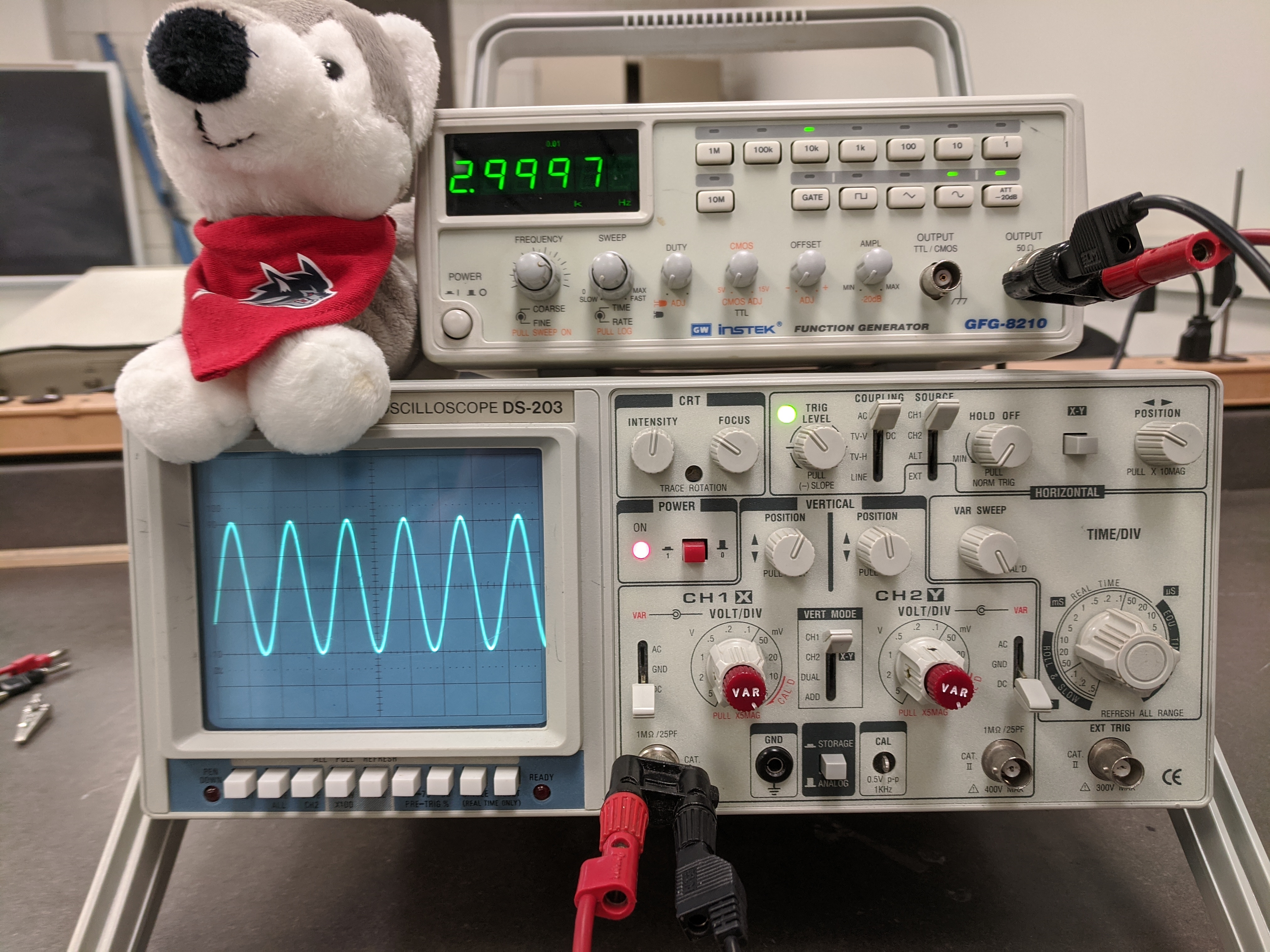
The Elenco DS-203 is an analog, Cathode Ray Tube (CRT) oscilloscope with 20 MHz bandwidth and 1 milliVolt sensitivity. It also has 2 channels of digital storage each of which can hold 2048 8-bit words, sampled at up to 10 MegaSamples per second.
The following instructions create a good starting point for any measurement using the oscilloscope. For any specific measurement, you will adapt the settings as needed. With the oscilloscope directly in front of you, set the controls as follows:
The white buttons below the display screen on the left should all be in the out position. The controls to the right of the screen should be adjusted as given below (cw means clockwise):
| Control | Setting |
|---|---|
| INTENSITY: | mid-range (line pointing up) |
| FOCUS: | mid-range |
| TRIGGER LEVEL: | mid-range |
| COUPLING: | AC position |
| SOURCE: | CH 1 position |
| HOLDOFF: | MIN (ccw) position, knob pushed in |
| XY: | button to the OUT position |
| POS: | mid-range |
| POWER: | button to the OUT position |
| POS ^ (Ch 1): | mid-range, knob pushed in |
| POS ^ (Ch 2): | mid-range, knob pushed in |
| VAR SWEEP: | calibrated (cw) position |
| AC AND DC (Ch 1) | switch to DC position |
| CH 1 knob: | set to 1 V(olt), VAR knob in CAL (cw) position |
| VERT MODE: | CH 1 position |
| CH 2 knob: | set to 1 V(olt), VAR knob in CAL (cw) position |
| AC GND DC (Ch 2): | set to DC position |
| TIME/DIV knob: | set to 0.1 (s) position |
| STORAGE/ ANALOG: | button to the OUT (ANALOG) position |