
Torque and Statics
In this lab, we will investigate the conditions for static equilibrium. Then, we will use those conditions and resulting relationships to determine an unknown mass.
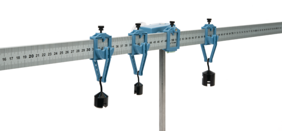
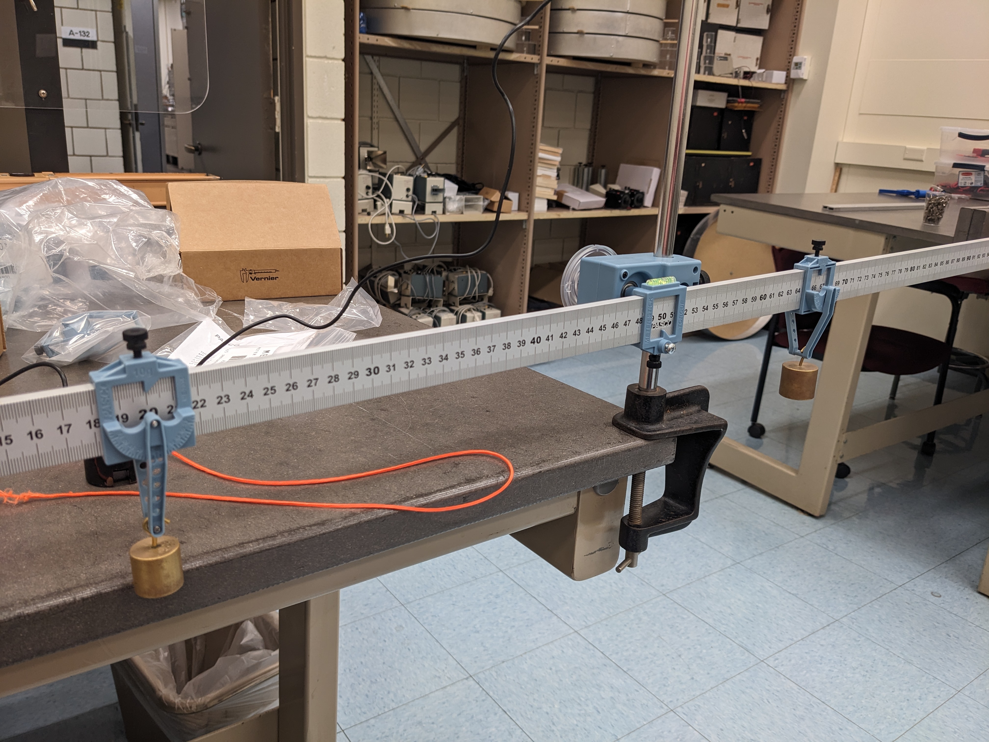
- Lab stand with a low friction, rotary lab stand mount for a meter stick
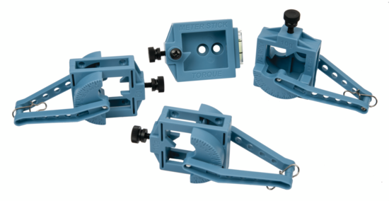
- 1 aluminum meter stick with hangers (10 grams each)
- Various known masses
At some point in an introductory physics course, after learning about kinematics and dynamics, in linear and circular motion, we get to apply this knowledge to an exciting and important application: systems that do not move1. This may seem disappointing at first but the study of static equilibrium (and extension into dynamic equilibrium) is crucial to any field where structures need to stay intact. This includes, but is not limited to, mechanical engineering, civil engineering, orthopedics and physical therapy.
In two dimensions (so, a 3-D object but only moving or rotating in one plane) the condition for static equilibrium of an object is that net forces and torques on that object are zero, ie:
$$\Sigma F_x= 0, \Sigma F_y= 0, \Sigma \tau= 0 $$To evaluate the torque about an axis (the point where the axis intersects the plane of rotation is the pivot or fulcrum ), we use
$$ \vec{\tau} = \vec{r} \times \vec{F}, \tau=rF\sin{\theta} $$where \(r\) is the moment arm, or distance from the point at which the force acts to the pivot. \(\theta\) is the angle between the force and a vector which points from the pivot to where the force acts (\(\vec{r}\)). The resulting vector torque \(\vec{\tau}\) points out, perpendicular to the plane created by \(\vec{r}\) and \(\vec{F}\). The cross-product relationship gives us that a torque pointing toward us seeks to create counterclockwise (ccw) rotation and a torque vector pointing away creates clockwise (cw) rotation. In cases where \(\theta = 90^\circ \), the torque is simply \(\tau=rF\); we take ccw as positive torque and cw as negative.
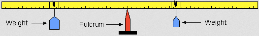
For Parts I and II of this experiment, one can simplify the problem even more. Masses hung to the left of the fulcrum experience a gravitational force which makes a counterclockwise torque on the system. Masses hung to the right of the fulcrum experience a \(\ F_{grav}\) which makes a clockwise torque on the system. It is the balancing of these torques which we investigate in Parts I and II.
We will be identifying positions along the meter stick as \( x \), such as \( x_{100 grams}\). In general, the relevant distance at which a torque acts, its moment arm \( r \) , is \( r = x_{where-torque-acts} - x_{pivotpoint} \) .
Part I: Balancing Torques
- Determine \( x_{pivotpoint} \)
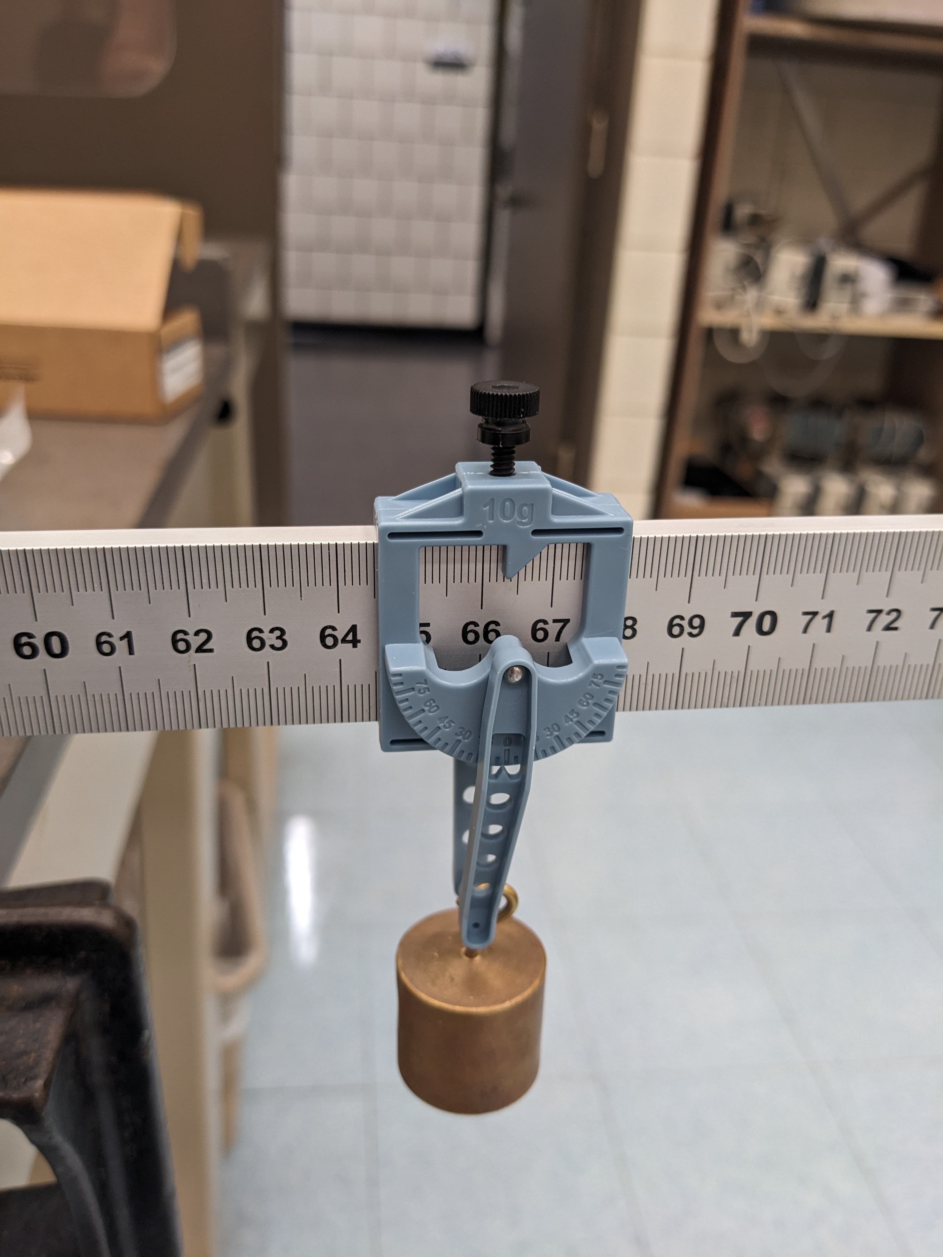
- Begin by sliding the aluminum meter stick into its low friction, rotary mount and balancing it in the mount. This will happen when the mount indicator is close to \(50\)cm; use the spirit level bubble to set this point carefully. Tighten the attachment screw then record the position.2
- Balancing Two Torques
- Slide a hanger onto the left (positions \(\lt 50\))cm side of the ruler and add a \( 100 \) gram mass to the hanger at \( x = 37 \)cm.
- Predict where a \( 50 \) gram mass should be position on the right side (positions \(\gt 50\)cm) to balance the system. Remember that the hangers each have mass of \( 10 \) grams.
- Slide a hanger and \( 50 \) gram mass on the right side of the meter stick and and adjust the position of the hanger until the system is balanced, ie. the meter stick is horizontal. Record the positions of each mass, with uncertainty.
- Repeat the above, except start with a 30 gram mass at \( x = 10 \)cm. Predict and then find the position where a \( 50 \) gram mass should be placed. Record the positions of each mass, with uncertainty.
- Draw a diagram of the set-up, including the forces acting on the meter stick.
- Balancing Three Torques
- Place two \( 20 \) gram masses (with hangers) on the left side of the meter stick, one at \( x = 10 \)cm and one at \( x = 20 \)cm..
- Predict where a \( 100 \) gram mass should be position on the right side (positions \(\gt 50cm\)) to balance the system. Remember that the hangers each have mass of \( 10 \) grams.
- Slide a hanger and \( 100 \) gram mass on the right side of the meter stick and and adjust the position of the hanger until the system is balanced, ie. the meter stick is horizontal. You might need to remove a mass from a hanger temporarily (or not ...) to fit on the third hanger. Record the positions of each mass, with uncertainty.
- Repeat the above procedure, except start with one \( 20 \) gram mass at \( x = 10 \)cm and one on the right side at \( x = 80 \)cm. Predict where a \( 50 \) gram mass should be place to balance the system. You might need to remove a mass from a hanger temporarily (or not ...) to fit on the third hanger.
- Draw a diagram of the set-up, including the forces acting on the meter stick.
Part II: Determining the Mass of the Meter Stick
In Part I, we centered the meter stick so that it did not contribute to the counter-clockwise (ccw) or clockwise (cw) torques. In this part, we will determine the mass of the meter stick by mounting it off-center and seeing what is needed to balance it.
- Method 1
- Remove the masses and hangers from the meter stick.
- While holding the meter stick up, slide the meter stick until the rotary mount is about the \( 70cm\) point. Now put a 100 gram mass and hanger on the right side hanger and slide until the meter stick balances. Record the balance point of the meter stick and location of the hanger plus 100 gm mass when the system is in equilibrium. Include uncertainties.
- Draw a diagram of the set-up, including the forces acting on the meter stick.
- Method 2
- Once you are done, Remove any hanger from the meter stick and remove it from the rotary mount. Weigh the meter stick on a scale and estimate the associated uncertainty.
Part I: Balancing Torques
For all of the mass combinations, calculate the positive (counter-clockwise) and negative torques on the meterstick plus masses system. Propagate errors. Did the measured location agree with the predicted location within experimental uncertainty? Show your work to justify your answer.
Part II: Determining the Mass of the Meter Stick
In our models, the weight of the meter stick is a force which acts at the center-of-mass, ideally, the \(50cm\) point. Starting with Newton's Second Law for Rotation ( the sum of the torques = \(\Sigma \tau =0 \) ), calculate the mass of the meter stick. Note that we place the fulcrum at \( x \approx 70cm)\).
Part 1: Balancing Torques
- How would the results have been different, if at all, if the meter stick had been balanced at 51 cm instead of at its center of mass? Justify your answer.
- How would the results have been different, if at all, if the meter stick had not been horizontal when it was "balanced"? Justify your answer.
Part II: Determining the Mass of the Meter Stick
- How would the results have been different, if at all, if the meter stick mount had had significant friction? Justify your answer.
- If the meter stick had been significantly heavier, do you expect that your results would have been more accurate or less accurate? Justify your answer using ideas from physics.
Hovering over these bubbles will make a footnote pop up. Gray footnotes are citations and links to outside references.
Blue footnotes are discussions of general physics material that would break up the flow of explanation to include directly. These can be important subtleties, advanced material, historical asides, hints for questions, etc.
Yellow footnotes are details about experimental procedure or analysis. These can be reminders about how to use equipment, explanations of how to get good results, or clarifications on details of frequent confusion.
For more about torque and static equilibrium, see KJF Ch. 7, plus Ch. 8.1 and 8.2.
You may find the Guide to Making and Using Plots
Value is from NOAA for Latitude: 40.91597332879679, Longitude: -73.12491620370486, MSL Height: 41.0 Predicted gravity: 980269 +/- 2 milligals where a "gal" is a centimeter per second squared
For an object moving at a non-constant speed in a circle, that formula still holds for the component of force perpendicular to motion, but there is also a component of force parallel to motion to change the speed.
Slightly more accurately, we work with three components: a vertical component, a radial component, and a tangent (parallel to velocity) component. But there are no forces in the tangent direction (we aren't varying speed), so there's no reason to discuss it.
For convenience, we'll say "radius" to refer to \(R\), even though it's not really the radius (since \(r\) is actually the radius of orbit).
We can fix the length above the tube by fixing the length below the tube. This is where the "cord clamp" comes into play: by spinning with it located some fixed, known length below the bottom of the tube, we can also have a fixed, known length \(R\) above the top of the tube.
Take your uncertainty in these position readings to be at least 1 mm.
To stay in cgs, use \(g= 980 cm/s^2 \) and convert Force to whatever the cgs unit is.
So, to reiterate, make sure all of the following are true:
- The clamp remains steadily ~1cm below the bottom of the tube. Under no conditions should it ever touch the bottom of the tube during the time you are measuring.
- Your hand should only touch the tube, and no other part of the apparatus during the experiment (in particular, not touching the string) while measurements are taken.
- The stopper is swinging approximately in a horizontal plane.
- The hanging washers should not be swinging (much).
Hook down also works if you tie the string to the tightening screw.