
e/m Ratio of the Electron
In this lab, an electron beam will be accelerated through a known voltage and then ejected into a magnetic field of known strength. Because of the magnetic field, the beam will then travel in a circle in accordance with the right hand rule (RHR) you have learned in class. We will use the radius of this circle to determine the charge-to- e mass ratio, \(e/m\), of the electron.
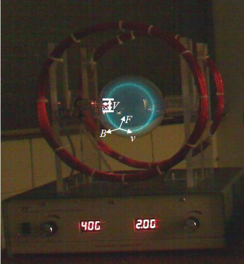
- One e/m apparatus consisting of:
- One set of Helmholtz coils (wires & mount)
- Two DC power supplies (one for current in coils, one for accelerating voltage)
- One vacuum tube (with some low-pressure Helium gas)
- One electron gun
- One light-blocking hood
- One compass rose (w/ marking for magnetic North)
Calculating e/m
In this lab, we'll be using the magnetic force equation \( \vec{F} = q\vec{v} \times \vec{B} \) and the centripetal force law from classical mechanics, \( F_C = mv^2 /R \).
Let \(B_⊥\) denote the component of the magnetic field perpendicular to the plane of motion of the electron. Since the component of \(F_C\) in the inwards direction is made by \(B_⊥\) (check this with the RHR!), we can ignore the other components of magnetic field. Since the inward magnetic force is the centripetal force and |q|=e, we must have: $$ mv^2/R = q\vec{v} \times \vec{B} = evB_⊥ $$
This would be nice if we knew the velocity. Fortunately, we know the voltage through which the electrons are accelerated. From electrostatics, we can set the change in electrical potential energy equal to the final kinetic energy of the electrons (work-energy theorem), to give; $$ W = qV = eV = ∆KE = \frac{1}{2}mv^2 $$
From this point, some algebra lets us eliminate the velocity variable entirely, giving us: $$ e/m = \frac{2V}{(rB_⊥)^2} $$
Helmholtz Coils
We'll be generating our magnetic field using a set of loops called a Helmholtz coil which consists of two circles of wires (each with \(N = 130\) turns of copper wire) specially configured to have their radius “\(a\)” equal to the separation distance between them. This makes the magnetic field in the center of the pair of coils as close to constant as possible.
In general, we know that magnetic field is proportional to the current that generates it as shown by this linear relation: $$ B = αI $$ The constant of proportionality α in general depends on the geometry of the wires making the magnetic field and the point at which you measure the field. If we measure the field at the center of a Helmholtz coil of radius a with \(N\) turns, the constant \(α\) is: $$ α= \frac{8}{5\sqrt{5}}\frac{μ_0 N}{a} $$ .....meaning that our final equation for \( e/m\) will be: $$ e/m = \frac{2V}{ α (Ir)^2} $$ (where r is the radius of the electron beam you will determine by carefully observing the beam and reading its diameter inside the coil). When written in the form we will plot to observe a realistic linear relation, it will become: $$ V = \frac{α^2}{2} \frac{e}{m}(Ir)^2 $$
Procedure:
First, use meter stick and measure the diameter, \(2a\), of the Helmholtz coil. Estimate an uncertainty on this value and then calculate the radius and propagate uncertainty.
Next, plug in and turn on your machine and wait 30 seconds it takes to boot up. Drape the hood over the top of the machine, if it is not there already. Turn your voltage and current knobs until you see a green circle of light illustrating the electron beam (about 200V and 1.5A are a reasonable starting point). This circle may be dim, so look closely! It is easiest to see where it crosses the measuring rod in the center.
Now: let's figure out which direction the magnetic field from the Helmholtz coil points. We will deduce this from how the electrons move. One fact you need to know about the machine's setup to make this deduction: the electrons in the electron beam travel in a clockwise direction, when the machine is viewed from the front (i.e., from the side with the digital displays) [Note: this is talking about the electrons in the illuminated green beam, not the electrons in the loops of wire].
With this information and your general knowledge of physics (including, but not limited to, the RHR), deduce the direction of the magnetic field made by the Helmholtz coil . Now, we want to align the machine so that the magnetic field generated by the machine is perpendicular to the magnetic field made by the Earth (we want to be able to ignore the magnetic field of the Earth in our experiment, which we can more-or-less do if our magnetic field of interest is perpendicular).
A few notes on how to do that. The building is more-or-less aligned with the cardinal directions, with one wall marked as true N. You should first align your compass rose so that N on the compass rose points to true north. Then, the compass rose will give you the direction of magnetic North/South, which of course is aligned with the Earth's magnetic field (neglecting vertical components). That, combined with your deductions above, should give you enough information to align your machine so that its magnetic field is orthogonal to the Earth's. Do so.
Now, it is time to actually take measurements of the electron beam. Choose a value for current, and adjust your voltage until the beam is centered on the smallest marker. The marker tells you the diameter, in cm; record the diameter, the current, and the voltage (with associated uncertainties). Then, increase the voltage until you hit the next marker, and again record the same quantities. Repeat until you hit the largest marker. Then, choose another value for current, and repeat the process (again, for a variety of radii). You can stop when you get sufficiently many data points.
Summary:
- Choose an \(I\) such as \(1.5\) Amps. Adjust \(V\) to give the beam a diameter so that it hits a marker (ie. every \(0.5\) cm). Record \(I\), \(V\) and \(d\). Do this for several values of \(V\).
- Choose a new \(I\). Repeat the above. Then, repeat again for a third value of \(I\).
Evaluate the Data:
- First, from coil diameter, calculate coil radius, \(a\). Then, calculate \(α\) and its uncertainty.
- For each data point, calculate \(r\) from the beam diameter, then calculate \((Ir)^2\) . Propagate all uncertainties.
- Finally, make a plot of \(V\) versus \( (Ir)^2\) . From the slope and your calculation of \(α\) , determine a measurement of \(e/m\).
Your TA will ask you to discuss some of the following points (they will tell you which ones):
Questions:
- Compare your value of \(e/m\) to a value from a trusted source. Do they agree to within experimental uncertainty?
- (A) Derivation of Eq. (3)
- Basic physics principles: Justify equations (1) and (2) in your own words.
- Doing the algebra: From equations (1) and (2) , show that equation (3) holds.
-
(B) Click here for a calculus problem
(B) Calculation of B Field of Helmholtz Coil:- B field of a ring: Using the Biot-Savart law, calculate the formula for the magnetic field on the z-axis generated by N turns of wire forming a ring of radius R that lies in the xy plane, through which passes a current I.
- B field of two rings: Now consider a general "Helmholtz-like" setup: consider two parallel rings both with \(N\) turns, radius \(R\) and current \(I\). Suppose they lie in the planes \( z = ± a/2\). Using the formula for the magnetic field of a ring, compute the magnetic field of this configuration on the \(z\)-axis [you can just use your answer to the previous part and the principle of superposition; you don't need to use Biot-Savart again].
- Why Helmholtz is Special: Compute the second derivative of that formula with respect to \(z\) at \(z=0\) (you may use Wolfram|Alpha to do this calculation). For what value of \(R\) does this second derivative vanish? What does that imply about the magnetic field near the center? How does this serve to explain why a Helmholtz coil is set up the way that it is?
- Final Result (deriving eq. (5) ): Take the result for the \(B\) field of two rings that you derived above and set \(R=a\) and \(z=0\). Show that you get equation (5) (with the definition of \(α\) from (4).
- (C) Other Magnetic Fields: First, based on your value for α and a typical value from your data for \(I\) in this experiment, compute \(B_{HH} \), the magnetic field of your Helmholtz Coil. Then, compare it to...
- Earth's field: The horizontal component of the Earth's magnetic field is about 20μT. We avoided this impacting our experiment by orienting our machine correctly. Based on how this field compares to the field of our Helmholtz coil, is that a necessary course of action, do you think?
- Other coils: The coils don't only have magnetic fields inside; they make magnetic fields at some distance, too. Consider the magnetic field of the people across the table from you, and consider their coil as a magnetic dipole some distance away. First, compute the magnetic moment of it, based on the current, number of turns and (an estimate of) area. Then, using that magnetic moment, an estimate of how far apart your coil was from theirs, and the formula for the magnetic field of a magnetic dipole, get an order-of-magnitude estimate for the magnetic field that their wires caused at the center of your coil (as a "cross-talk" effect). Is this large enough to be concerned over in this experiment?
- (D) Experimental limitations: Why is it far easier to measure e/m experimentally than either e or m individually (not just with this experiment, but with any setup)? Note: "the numbers involved are small" is not a complete answer; while that has elements of the truth, there's a deeper reason that you should get at.
- (E) Using Protons: Suppose we were to attempt to use a similar machine to measure the charge-to-mass ratio of protons, instead. Suppose, for simplicity, that we can get a "source" for a beam of protons as we do here for electrons (with a similar setup). What complications (if any) do you expect?
- (F) Variation in B: At the edges of the coil, the deviations of the magnetic field from the value at the center is approximately 7%. This is an unaccounted-for uncertainty in our experiment. How does this compare to the other uncertainties you have in this lab?
References and Tools