
Refraction and Snell's Law
The purpose of this lab is to explore the concept of refraction, how the speed of light varies in different media, and how this affects the path of light through these media. You will examine the relationship among the angle of incidence, angle of refraction, and the index of refraction for two different media. You will also determine the focal lengths of a converging and diverging lens. Lenses form images from refracted light rays.
- Optics kit with prisms and lenses
- Laser pointer
- Laser ray box
- Semi-circular dish filled with water
- Ruler and protractor
- Record data in this (draft) Google Sheets data table
Click here for an image of the Rectangular Block set-up
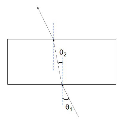
- Place the rectangular acrylic block on a piece of graph paper and trace its outline. Place it aside.
- Select a normal line to the outline of the block’s surface. The line should be approximately at the center of the block’s face.
- With your protractor, draw a line of incidence to the same normal line, using angle \(\theta_1\) of 20.0°, as shown in Figure 2. Label the angle carefully. Place the block in the previously traced outline.
- Using the laser pointer, shine the red light ray along the drawn line that forms a 20.0° angle of incidence. Looking at the block from above, observe the bending of the light ray in the block and its emergence on the other side. Trace the emerging ray with your ruler. \(\theta_1\)
- Remove the block and connect the incident and emerging ray. See Figure 2
- Measure the angle of refraction \(\theta_2\) and record your data in Table 1. Make sure you measure the angle the refracted ray makes with the normal line. Estimate the error of each angle of incidence and refraction based upon the precision of your protractor, for example, ±0.5° or ±1°.
- Calculate the sine of each angle and record in Table 1.
- Repeat the experiment with three other angles of incidence, for example, 30.0°, 40.0°, and 50.0°.
- The following equation (Eq. 4) may be used to estimate the uncertainty of each angle in radians (use the appropriate uncertainty from your protractor): $$\delta \sin(\theta) = (0.5° * \frac{\pi}{180°}) \cos(\theta) $$
Construct a graph of \(\sin(\theta_2)\) vs. \(\sin(\theta_1)\). Record the slope of the graph and propagate the error.
Q1: What is the index of refraction of the acrylic block?
Q2: What is the speed of light in the acrylic material?
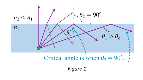
Q3: Calculate the critical angle at the acrylic-air interface.
Click here for an image of the Water set-up
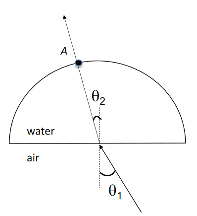
You will now measure the index of refraction of water, using a similar procedure as the previous part. This time you will use the semi-circular dish filled with water. The index of refraction will be determined from experimentally measured angles of incidence and refraction.
- Place the semi-circular dish on the graph paper on the following page and trace its outline, as shown in Figure 3. Place it aside.
- Select a normal line to the outline of the dish’s surface. The line should be approximately at the center of the straight edge.
- Repeat the procedure from the previous part, shining the light ray incident on the flat surface with a pre-measured angle \(\theta_1\) that is clearly labeled on the diagram. Shine water the laser so the ray aligns with the angle of incidence you have drawn.
- The dish has a protractor on its bottom surface, so you may measure the angle or refraction \(\theta_2\) for the laser ray.
- Estimate the error of each angle of incidence and refraction based upon the precision of your protractors, for example, ±0.5° or ±1°.
- Repeat the experiment with three other angles of incidence. Record your data in Table 2.
Construct a graph of \(\sin(\theta_2)\) vs. \(\sin(\theta_1)\). Record the slope of the graph and propagate the error.
Q4: What is the index of refraction of water?
Q5: What is the speed of light in water?
Q6: Explain why the refracted ray does not change direction when it re-enters air at Point A.
Q7: Calculate the critical angle at the water-air interface.
Click here for an image of a converging lens
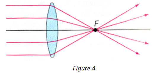
- Place the convex lens on a white sheet of paper and trace the outline of the lens. Draw a line down the center of the lens.
- Position the laser ray box 2-3 centimeters from the center of the lens. Switch on the box with 5 parallel beams.
- With your ruler, trace the refracted rays on the opposite side of the side of the lens.
- Estimate the focal length and approximate error of the converging lens, using the correct sign convention. Determine the error based upon your estimated precision, for example, ±1mm or ±5mm.
Q8: What type of image is always produced by a converging lens if an object is positioned between the focal point and the lens? Real or virtual? Inverted or upright? Reduced or magnified?
Q9: What type of vision defect is corrected with a converging lens?
Click here for an image of a diverging lens
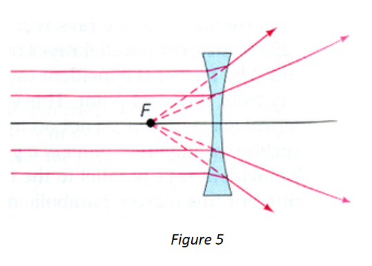
In this part you will determine the focal length a concave lens. Since the lens has an index of refraction higher than air, light rays will refract. In this case, the rays diverge along the plane of the focal point on the same side of the lens, as shown in Figure 5.
- Place the concave lens on a white sheet of paper and trace the outline of the lens. Draw a line down the center of the lens.
- Position the laser ray box 2-3 centimeters from the center of the lens. Switch on the box with 5 parallel beams.
- With your ruler, trace the refracted rays on the opposite side of the side of the lens.
- Remove the lens and carefully trace the refracted rays to the opposite side of the lens (where the laser ray box was originally positioned).
- Estimate the focal length and approximate error of the diverging lens, using the correct sign convention. Determine the error based upon your estimated precision, for example, ±1mm or ±5mm.
Q10: What type of image is always produced by a diverging lens? Real or virtual? Inverted or upright? Reduced or magnified?
Q11: What type of vision defect is corrected with a diverging lens?