
Fluids

The purpose of this lab is to explore properties of fluids in static and dynamic situations.
In Part 1, you will employ Archimede's Principle to determine the density of a known material. Then, using the same technique, you will seek to identify and unknown material.
In Part 2, you will observe that flow through small capillaries will be non-ideal. The viscosity of the fluid leads to a behavior where the pressure difference across the capillary is proportional to the flow rate through it. Hoveroverthese
Equipment
- Part 1: set-up with hanging scale, graduated cylinder, Al mass, unknown mass
- Part 2: set-up with connected graduated cylinders, valves, capillary tube and timer
In studying introductory physics, we typically start by treating objects as single points, which can translate in one or more dimensions. Next, we allow objects to have an extent which can rotate (as well as translate). Up to that point, all materials we consider are solids, which do not change shape when moving.
To prepare for the next level of complexity, we need the definition of pressure: \(P\) is the Force per unit Area exerted on one part or the whole of an object \( P= F/A \). Most textbooks then consider the deformation (compression, extension, shear) of solids and the pressure required to cause the material to exceed its elastic limit and fail.
Liquids and gases are examples of fluids1, which flow under a pressure or, if confined, transmit that pressure throughout the fluid volume. In this experiment we will investigate a liquid (water) which we will treat as an incompressible fluid (also non-viscous, until Part II).1.
In the motion of an incompressible, non-viscous fluid, we have conservation of energy. Combining this with the conservation of matter (ie. the fluid does not evaporate or react chemically) we arrive at the Bernoulli equation and Continuity condition relating conditions at points 1 and 2 in the system. \(P\) is the measured pressure, \(\rho\) is the density1, \(v\) the fluid velocity and \(A\) the area of the flow (ie. pipe inner area)2.
$$P_1 + \frac{1}{2} \rho v_1^2 + \rho gy_1 = P_2 + \frac{1}{2}\rho v_2^2 + \rho gy_2 $$ $$A_1 \rho_1 v_1 = A_2 \rho_2 v_{2} $$In Part I we will deal with a special case: hydrostatics. In this situation the velocity terms in Bernoulli's Equation are zero. The hydrostatic term, \(\rho gh\) and Pascal's Principle (any outside pressures act throughout the fluid) combine to give Archimede's principle: if \(V_{displaced}\) is the volume of fluid displaced by an object then the buoyant force is given by
$$ F_{buoyant} = \rho_{displacedfluid} \, g V_{object} $$In Part II we look at a deviation from Bernoulli for non-ideal fluids which exhibit viscosity but do not undergo turbulence. An important example of this is blood flow in the human arterial system2. A simple model for viscous fluids is to assume laminar flow; this works for a regime of flow where the Reynold's Number is low. Internal friction in the fluid leads to energy loss, which can be seen as a pressure difference across a small pipe (or capillary) which depends on the flow rate. The Hagen-Poiseuille's Law states that the volume flow rate \( Q = \frac{dV}{dt}\) through a small pipe depends on length \(L\), pipe radius (\(r\)), the pressure change \(\Delta P\) and the dynamic viscosity of the fluid \(\eta \)3 in the following way:3:
$$ Q = \frac{\pi r^4 }{8 \eta L} \Delta P $$
Part I: Buoyancy and Archimede's Principle
Part II: Poiseuille's Law
In this experiment, a fluid is forced to flow through a small capillary by hydrostatic pressure. The capillary is chosen so that water will exhibit nearly laminar flow and obey the Hagen-Poiseuille law. As the experiment progresses, the change in column height (and, therefore \(\Delta P\)) is related to volume flow \(Q = \frac{dV}{dt}\) by that law.
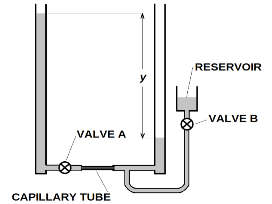
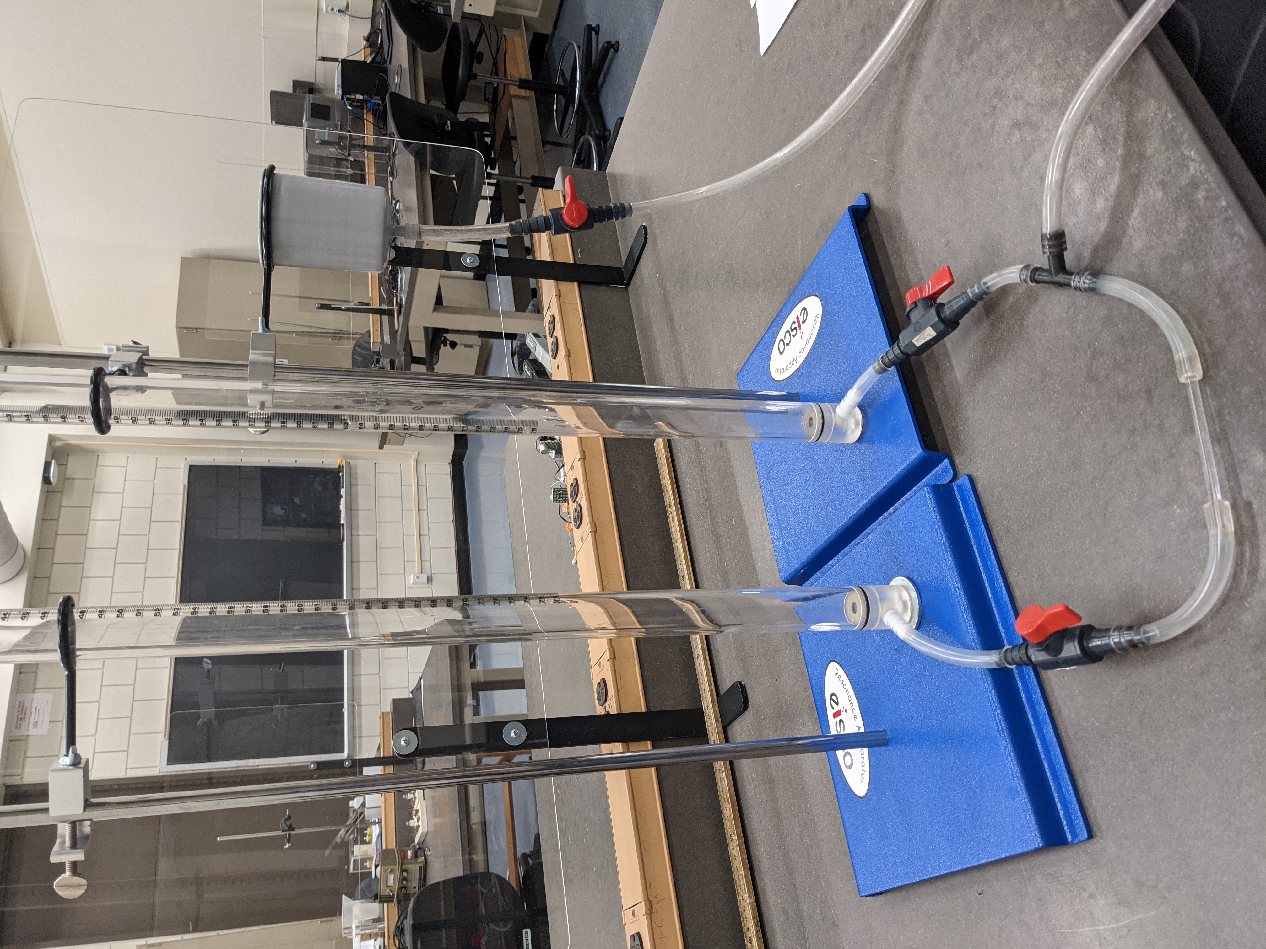
- Flow valve A was left open (with reservoir valve B closed) for a long time prior to beginning your experiment, allowing the water levels to equilibrate in the vertical tubes. We will close valve A, open valve B and adjust the height of the reservoir cup until the water level in the columns is 25cm, then close valve B.
- Next we carefully pour water into column 1 until \(y_1 \approx 75\)cm. Record these two levels. The difference between the two values (\(y_1 -y_2\)) is the initial height difference \(y_0 \approx 50\)cm.
- Simultaneously start a timer and open valve A; the water level in the higher column should start dropping and the lower column should start rising. Record the \(y(t)\) and the elapsed time \(t\)4 at 30 second intervals until the difference in heights between the two water columns \( y \lt 5 \) cm. Record the Celsius temperature in the lab room.
Part I: Buoyancy and Archimede's Principle
Answer the question about agreement with expectation.
Part II: Poiseuille's LawCalculate \(y/y_0\) for each time interval. Propagate uncertainty. Calculate \(ln(y/y_0)\) and assign the same relative uncertainty as for \(y/y_0\).
Make a plot of \(ln(y/y_0)\) vs. elapsed time \(t\). The slope should be 4 $$ Slope = - \frac{\pi r^4 ρ g}{A_{cyl} 8 \eta L} $$
Use your slope, radius of the capillary \(r_{capillary} = 0.5 \)mm, length \(L_{capillary}= 10\)cm, area of the graduated cylinder \(A_{cylinder} = 5.0 \)cm2 and the density of water \(\rho\) to extract a value for \(\eta\), the viscosity of water. Assume all quantities in Equation 10 have small (negligible) uncertainty except the slope of the graph. Compare to the accepted value obtained using room temperature T (in \(^\circ\)C): \(\eta = 1.002 + .024(20- T) x 10^{-3}\)Pa-sec.
Answer the following questions in your lab notebook:
Your TA will ask you to discuss some of the following points (they will tell you which ones):
- Systematic Error: Mass of the ribbon: The mass of the ribbon used to connect the weights (paper clips) is small but not zero. What is the impact of this mass on Part I of our experiment?
- Derive Equation 7: Make a Free Body Diagram on the balloon to show how we arrived at Equation 6. Then combine Equations 6 and Archimede's Principle (Equation 3) and derive Equation 7.
- Systemic Error: Uniformity of Temperature: We assumed that the air and water were at the same temperature in Part III. Estimate how large would the effect be if the tap water used for Part III was ~45\(^\circ\)F.
- What is Air? If the result in Part I is sufficiently precise, we can rule out the possibilities that air is purely Oxygen or purely Nitrogen. Show that the value we used for molar mass of air is consistent with the gas composition of air we expect.
- Height of the pipe ends in Part II A feature of the simulation we did not use is that the pipe ends may be raised and lowered. If we made the pipe ends at different heights, how would our results for testing the Bernoulli Equation and Continuity expression be affected?
- Temperature correction in Part III Is our inclusion of a temperature dependence of viscosity \(\eta\) necessary in this experiment? make a quantitative argument why or why not.
- Other hydrostatic terms in Part III We did not specify or measure the vertical distance above the ground or below the "25cm" column water level for the capillary. Comment, quantitatively would be preferred, on whether this is justified.
Hovering over these bubbles will make a footnote pop up. Gray footnotes are citations and links to outside references.
Blue footnotes are discussions of general physics material that would break up the flow of explanation to include directly. These can be important subtleties, advanced material, historical asides, hints for questions, etc.
Yellow footnotes are details about experimental procedure or analysis. These can be reminders about how to use equipment, explanations of how to get good results, or clarifications on details of frequent confusion.
For a review of ideal fluids, see Knight, Jones and Field Chapter 13.
These equations are Eqtn 13.12 and 13.14 in KJF, with density \(\rho\) being constant.
For more on non-ideal fluids, see Knight, Jones and Field Chapter 13, Sections 7. An excellent alternative resource is HyperPhysics on Laminar Flow and other links therein.
For a review of ideal gases, see Knight, Jones and Field Chapter 12, especially equation 12.12
In general, the density \(\rho \) can be different at points 1 and 2 but will be the same for our experiment.
See HyperPhysics on Blood Flow
This law is derived assuming flow velocity of zero at the tube walls rising to maximum in the center of the tube. The flow is assumed to be laminar, ie, same for any value of radial position and only axial flow.
The natural logarithm appears because flow rate depends on how much has already flowed through the capillary. This occurs in population growth and radioactive decay: when rate is proportional to the number then one gets an exponential rise or fall.
The Helium we use comes from our legacy stock, used with the Physics Dept liquifier. It is quite pure, likely 99.5% or better. The contaminants include compressor oil, "light ends" (volatile ethers and ketones) and other chemical which none of us should breath. Also note, He gas in "party store" balloons is ~80% pure and contains some air and some unpleasant chemicals. Creating a funny voice for a few seconds is not worth exposure to unknown materials!
\(m\prime \) is often called the "apparent mass" or, colloquially, the "weight under water".
When this apparatus is used for a full lab we often investigate the effect of putting multiple capillaries together in series or parallel.
The best way to perform this, with two people, is to stop the timer and simultaneously close Valve A. After recording \(y_1\), \(y_2\) and \(t\), re-start the timer (without resetting the timer to zero) while simultaneously re-opening valve A. Repeat this every 30 seconds. Since this lab is "simulated" we have simplified some details.