
Series and Parallel DC Circuits
The purpose of this lab is to study the potential difference and resistance across various points in series, parallel and combination circuits. You will verify the validity of the expressions for total resistance in each circuit.
Components in an electrical circuit are in series when they are connected one after another, so the same current flows through them. Components are in parallel when they are in alternate branches of a circuit. When the resitors are connected parallel the voltage drop on all of the resistors is the same. Series and parallel circuits function very differently. For example, when using some types of older decorative holiday light circuits, if one lamp is removed, the whole string of lamps goes off. These lamps are in series. When a light bulb is removed in your home, the other lights stay on, because household wiring is normally in parallel.
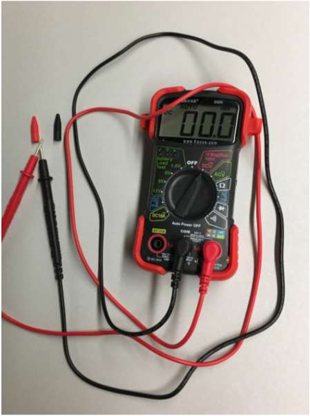
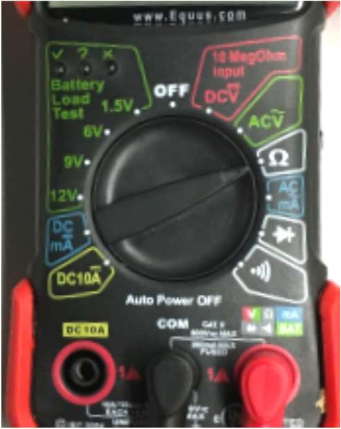
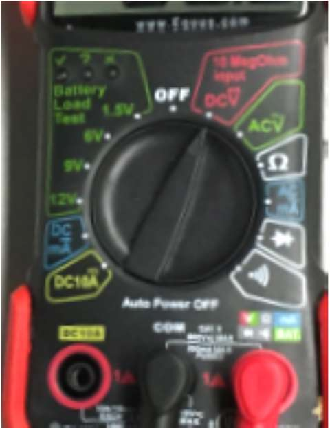
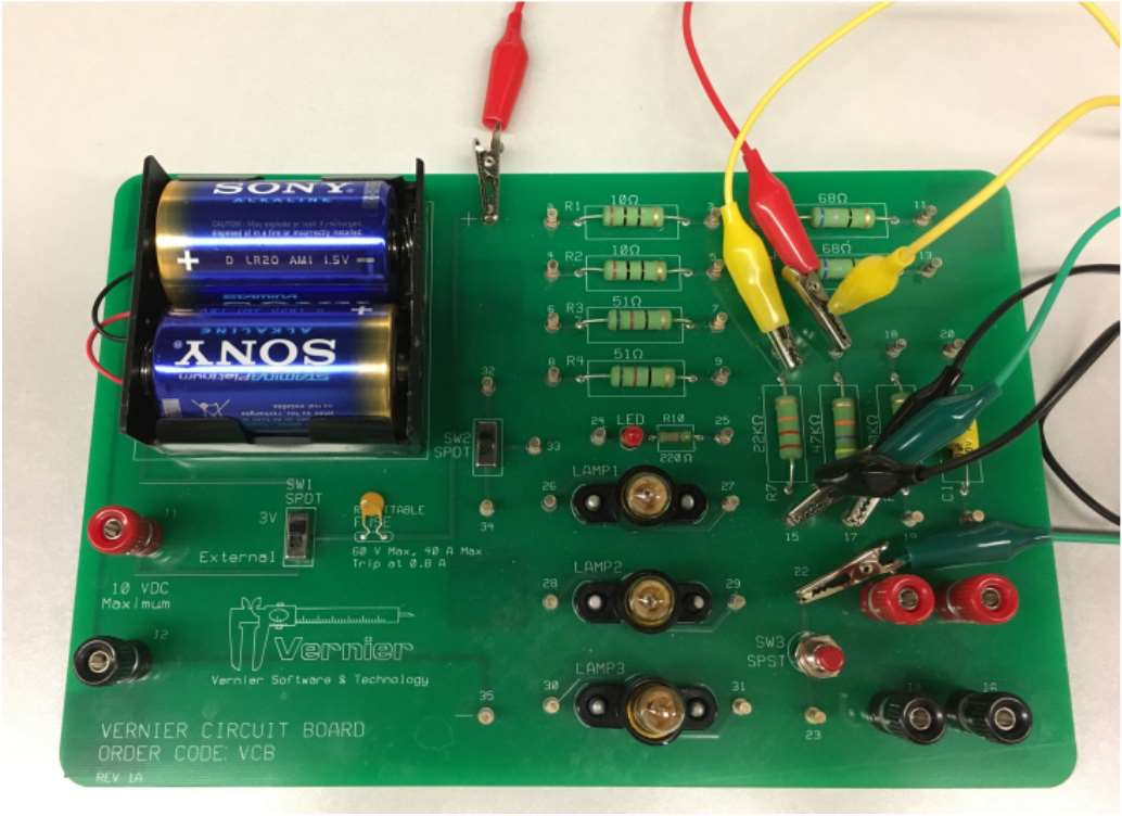
In this lab we will be using a simple digital multimeter to measure voltage and resistance. The meter has a red and a black probe. These probes have to be connected to the meter as shown on the photos here. We will use two settings. The “DCV” setting (on the right) is to measure voltage and the "\(\Omega\)” setting (on the left) is for measuring resistance.
The goal of this experiment is to study circuits made up of two resistors in series or parallel. You can then use Ohm’s law to determine the equivalent resistance of the two resistors.
- Digital multimeter
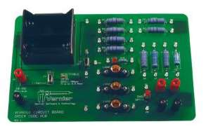
- Circuit board
In this part, you will connect and investigate two resistors in series. You will verify if the potential difference (voltage) on the two resistors add up.
Procedure
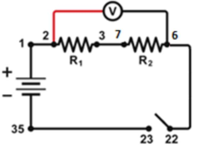
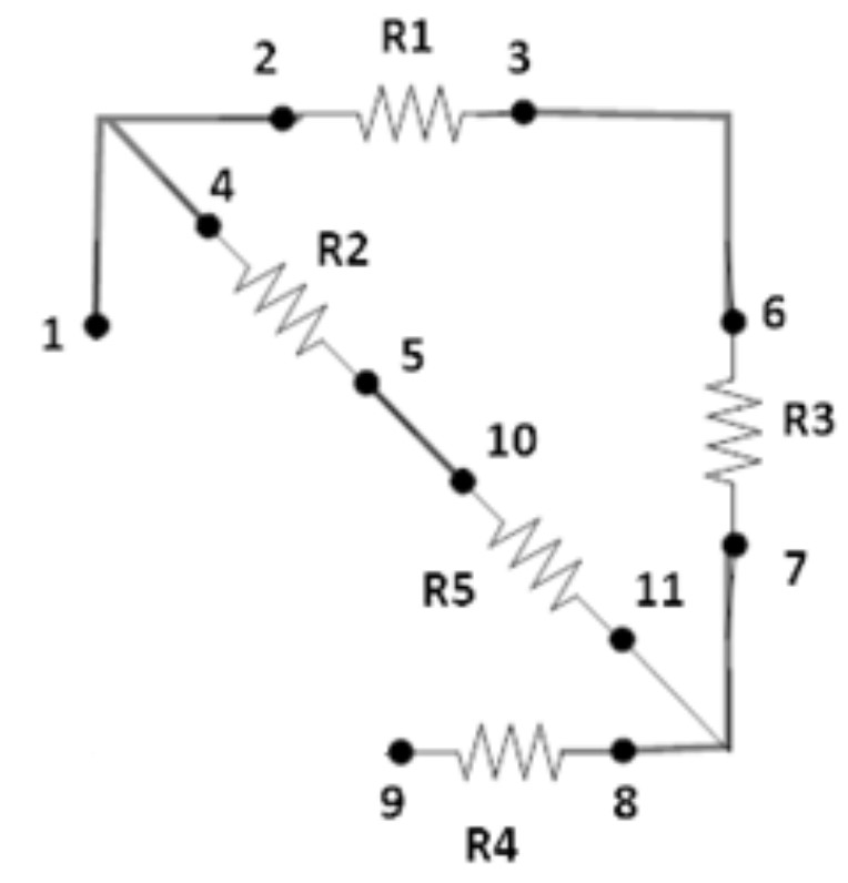
- Wire the two resistors, \(R_1\) and \(R_2\) , in series so that you obtain the circuit shown in Figure 3. Do not connect the voltmeter yet. Note: The numbers in Figure 1 refer to the numbered terminals on the circuit board.
- Set Switch 1, SW1, located below the battery holder on the circuit board to 3V.
- Have the instructor check the arrangements of the wires before proceeding.
- Switch the digital multimeter to the “DCV” settings. In this mode it measures the voltage between the terminals.
- Press the probes of the voltmeter to terminals 2 and 6 (as shown in Figure 1)
- Ask your lab partner to close the circuit by pressing the switch (in 22-23 terminals). Record the voltage in Table 1. We will call this \(V_{26}\) .
- Repeat the procedure using terminals 2 and 3, and record \(V_{23}\) .
- Repeat the procedure using terminals 7 and 6, and record \(V_{76}\).
- If any of the voltages is negative, check the position of the voltage probes. The red probe should be always closer to the positive terminal of the battery than the black probe. (“Close” in the sense of following the current flow in the circuit.)
- Estimate an error for the values of the measured voltage and current using any fluctuations of these values in the multimeter. If there are no fluctuations, the error is ± 1 of the last digit. For example, if the voltage is 12.27 mV, the error is ± 0.01 mV.
Evaluate the Data
| \(V_{26}\) in Volts | \(\Delta V_{26}\) in Volts | \(V_{23}\) in Volts | \(\Delta V_{23}\) in Volts | \(V_{76}\)in Volts | \(\Delta V_{76}\) in Volts |
|---|---|---|---|---|---|
| | |
Questions
Answer these questions:
- Does the \(V_{26} = V_{23} + V_{76} \) relationship hold?
- We call the resistance between terminals 2 and 6 \(R_{Total}\) . If the \(V_{26} = V_{23} + V_{76} \) relationship indeed holds, and the current flowing through resistor \(R_1\) is the same as the current flowing in resistor \(R_2\), what is the relationship between \(R_1\), \(R_2\) and \(R_{Total}\) ?
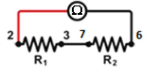
This time we will make a really simple circuit. We remove every other wires, except for the one connecting terminals 3 and 7, see Figure 2.
Procedure
- Switch the digital multimeter to the “\(\Omega\)” settings. In this mode it measures the resistance between the terminals.
- Measure the value of \(R_1\) by pressing the probes of the multimeter to terminals 2 and 3.
- Measure the value of \(R_2\) by pressing the probes of the multimeter to terminals 6 and 7.
- Measure the value of the series resistance \(R\) by pressing the probes of the multimeter to terminals 2 and 6 (see Figure).
- If your readout of the resistances did not fluctuate (they should not!), the error is ± 1 of the last digit.
- Record the values (together with units) in the first row of Table 2
- Connect the resistors between terminals 14, 15 and 16, 17 in series. To avoid confusion with the previous data, call the resistance between 14 and 15 \(R_1\)’, the resistance between 16 and 17 \(R_2\) ’ and the total resistance R’
- Repeat the same procedure to obtain \(R_1\)’, \(R_2\) ’ and R’ and record them in the second row of the Table.
Technical note: When you measure resistance with the simple method we use here, the measurement also includes the resistance of the lead wires and the contacts. Ideally, these resistances should be much lower than the measured resistance. When the measured resistor is in the 10\(\Omega\) range the contact resistance (how hard you press the probe to the terminal) may come into play. There is no such problem when the resistors are in the \(10^4 \Omega\) range (like \(R_1\)’, \(R_2\) ’).
Use this equation to calculate the total theoretical resistance you should obtain when you connect your two resistors in series and compare it with the total experimental resistance. $$ R_{calc} = R_1 + R_2 $$ To calculate the error of \(R\) : $$ \sigma R_{calc} = \sqrt{((\sigma R_1)^2 + (\sigma R_2)^2)} $$
Evaluate the Data
| \(R_1\), \(R_1'\) in \(\Omega\) | \(\Delta R\),\(\Delta R'\) | \(R_1\), \(R_1'\) in \(\Omega\) | \(\Delta R_1\),\(\Delta R_1'\) | \(R_2\), \(R_2'\) in \(\Omega\) | \(\Delta R_2\),\(\Delta R_2'\) | \(R_{calc}\), \(R_{calc}'\)in \(\Omega\) | \(\Delta R_{calc}\),\(\Delta R_{calc}'\) |
|---|---|---|---|---|---|---|---|
| | | |||||||
| | |
Questions
Answer these questions:
- Is the measured resistance the same as the value written next to it? If not, what can be an explanation? (Hint: these resistors are really cheap.)
- Is the experimental equivalent resistance R consistent with the calculated value \(R\) total ? (i.e. Are the two values equal within the experimental error?)
- When do you get better agreement with the theoretical value: If you use the measured resistances or if you use the values written next to the resistors?
In this part, you have two resistors in parallel. We will investigate the parallel circuit shown in Figure 3. In particular, we will see if the resistance of two in parallel resistors \(R_1\) and \(R_2\) satisfies $$ \frac{1}{R_{calc}} = 1/R_1 + 1/R_2 $$
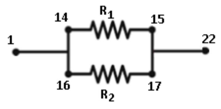
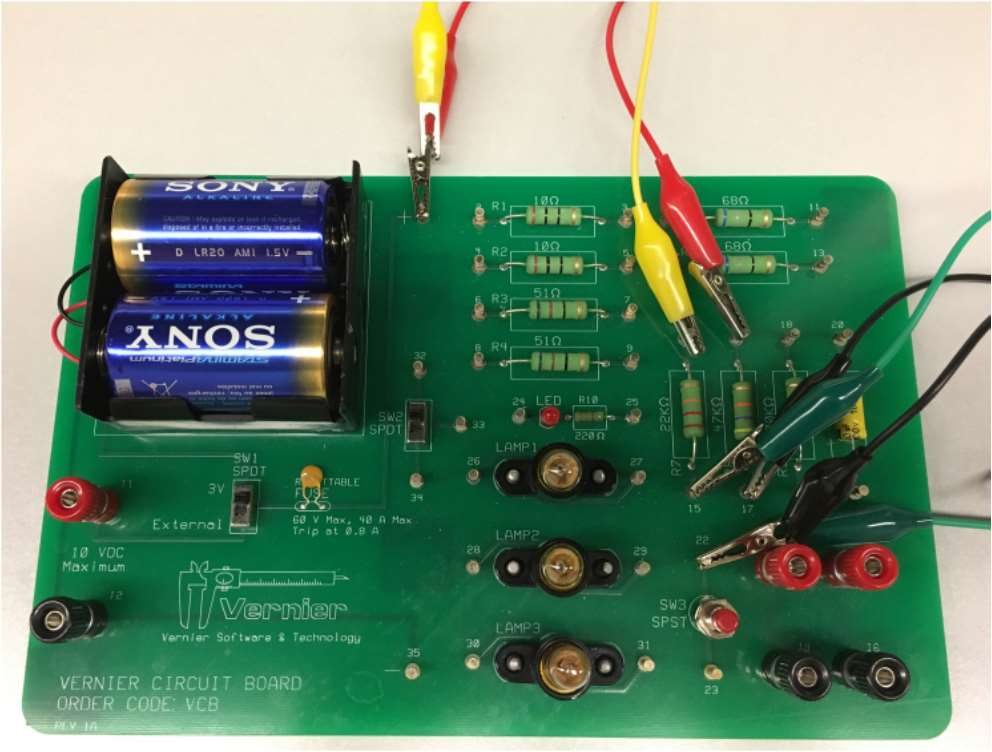
Please note that we have several different ways of setting up parallel circuits, and they are all equivalent, as long as the resistance of the lead wires is very much smaller then the resistance of the resistor we are dealing with. Under this condition, the electric potential difference between the terminals connected by wires is zero, and it does not matter how the connection was made. The photos below show two different ways of realizing the circuit shown in Figure 3 and there are many more ways to do this. The circuit in the right and left will have the same resistance between terminals 1 and 22.
Procedure
- Wire the two resistors, \(R_1\)and \(R_2\) , in parallel so that you obtain the circuit shown in Fig. 3. Note: The numbers in the Figure refer to the numbered terminals on the circuit board.
- Switch the digital multimeter to the “\(\Omega\)” settings.
- Using the multimeter, measure the resistance between terminals 1 and 22. We call this resistance R.
- Remove the connecting wires and measure the values of \(R_1\) and \(R_2\) separately.
- Record the values in Table 3.
- If your readout of the resistances did not fluctuate (they should not!), the error is ± 1 of the last digit. Record the error values in Table 3.
Evaluate the Data
| \(R_1\) | \(\Delta R_1 \) | \(S_1 = 1/R_1\) | \(\Delta S_1\) | \(R_2\) | \(\Delta R_2 \) | \(S_2 = 1/R_2\) | \(\Delta S_2\) | \(R\) | \(\Delta R\) |
|---|---|---|---|---|---|---|---|---|---|
| | |
The rest of Table 3 is filled out with calculated values. First, according to Eq. (2) we need to calculate the inverse of the resistances \(S_1 = \frac{1}{R_1}\) and \(S_2 = \frac{1}{R_2}\) . We note that the relative error of \(R\) and the relative error of \(S\) are the same. (This follows from the Power Rule for error propagation with exponent \(-1\)) Therefore \(\sigma R_1 / R_1 = \sigma S_1 / S_1\) and \(\sigma S_1 = S_1 (\sigma R_1 /R_1 )= \sigma R_1 /R_1^2\) . We have a similar expression for \(\sigma S_2\) .
Table 4 is filled out with calculated values. According to Eq. (2) \(S_{calc} = 1/R_{calc} = 1/R_1 + 1/R_2 \). The error in this quantity is \(\sigma S = \sqrt{\sigma S_1^2 + \sigma S_2^2}\) Finally, we calculate \(R_{calc} = \frac{1}{S_{calc}}\) and \(\sigma R_{calc} = \sigma S_{calc} /S_{calc}^2\) .
| \(S_{calc}\) | \(\Delta S_{calc} \) | \(R_{calc} = 1/S_{calc}\) | \(\Delta R_{calc}\) |
|---|---|---|---|
| | |
Questions
Answer these questions:
- Is the total experimental resistance \(R\) consistent with the calculated value \( R_{calc}\)?
In this part, you will connect several resistors in both series and parallel. You should be able to find the total calculated resistance by identifying which resistors are in series and which are in parallel. At the end, in your notebook, you will reduce the circuit with only one resistor and find this value by using equations (1) and (2).
Please note that we have several different ways of setting up parallel circuits, and they are all equivalent, as long as the resistance of the lead wires is very much smaller then the resistance of the resistor we are dealing with. Under this condition, the electric potential difference between the terminals connected by wires is zero, and it does not matter how the connection was made. The photos below show two different ways of realizing the circuit shown in Figure 3 and there are many more ways to do this. The cicuit in the right and left will have the same resistance between terminals 1 and 22.
Procedure
-
Wire resistors \(R_1\) =10Ω, \(R_2\) =10Ω, \(R_3\)=51Ω, \(R_4\) =51Ω,
and \(R_5 =68Ω\) as is shown in the following circuit.
- Switch the digital multimeter to the “\(\Omega\)” settings.
- Using the multimeter, measure the resistance between terminals 1 and 9. We call this resistance \(R\).
- Remove the connecting wires and measure the value of each resistor separately by pressing the probes of the multimeter to the terminals.
- Calculate \(R_{calc}\) using Equation (1) when the resistors are in series and (2) when they are in parallel. You will need to identify which resistors are in series and which are in parallel. Draw equivalent circuits until you get the final circuit with only one resistor.
- Do not calculate errors for this part.
Questions
Answer these questions:
- Is the total experimental resistance \(R\) consistent with the calculated value \(R_{calc}\) ?
- Why was it important to remove the connecting wires before measuring the individual resistances?