
Angular Momentum
Equipment
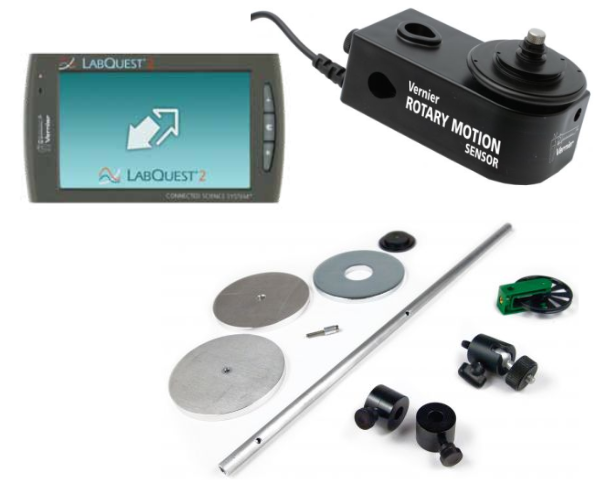
- Vernier rotary motion sensor with accessory kit
- Vertical support rod
- LabQuest 2
- Scale and ruler
In this experiment we will investigate the conservation of angular momentum . The definition of angular momentum L is $$ L = I\omega $$ where \(I\) is the moment of inertia for the object and \(\omega\) is its angular velocity.
We will test whether angular momentum is conserved before and after a collision, using the relationship $$ I\omega = I′\omega′ $$
The dashed quantities refer to the angular momentum and angular velocity in the final state (after collision), and the undashed quantities refer to same variables in the initial state (before collision).
In order to increase the moment of inertia of the rotating object we will drop an aluminum disk onto the rotating platform, thus changing the moment of inertia, and measure the angular velocity \( \omega \) before and after the drop.
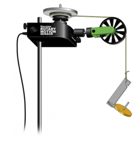
The apparatus used for this lab is sketched in the figure below. The Vernier rotary motion sensor is a bidirectional motion sensor that measures angular motion precisely and plots angular displacement, angular velocity and angular acceleration vs. time. This sensor is direction sensitive, meaning the signs of the vectors depend on the direction of the rotation of the sensor. For this experiment, we do not need to record the sign of each quantity, only the absolute value.
Determination of \(I\), the Moment of Inertia for the Platform
Often we determine the moment of inertia for an object by calculation, using the definition:
$$ I = \int r^2 dm $$However, the platform of the Rotary Motion sensor is a complicated thing: it has an aluminum disk, some plastic pulleys and bearings, all with different sizes and mass distributions. This makes calculation very difficult. So, the method to find \(I\) is to measure an applied torque \(\tau\) and the resulting angular acceleration \(\alpha\). We then find the moment of inertia from
$$ I = \tau/\alpha $$ We have done that processs for you and have values for \(I\) and \(\Delta I\). Please ask for the best values to use1.
Testing of Conservation of Angular Momentum for Aluminum disks collision
Now, we will perform an experiment in which we change the initial moment of inertia by dropping an additional disk on top of the rotating platform. This drop (if done carefully) does not cause an external torque which would modify the initial angular momentum.
The final, or total, moment of inertia \( I′\) is equal to the sum of \( I\) (moment of inertia of the platform) and \(I_{disk}\) , the moment of inertia of the dropped disk.
Measurements for \( I_{disk} \)
- Measure the radius \( R \) of the disk with the ruler and use \(0.5\) mm for its absolute error.
- Measure the mass of the disk \( M\).
The Collision
- Spin the rotating table. Press the “Collect” button, while the rotating table is spinning and drop the wide-‐hole aluminum disk.
- Go to the “Graph” screen and you should get an angular velocity vs. time graph that
looks roughly like this:
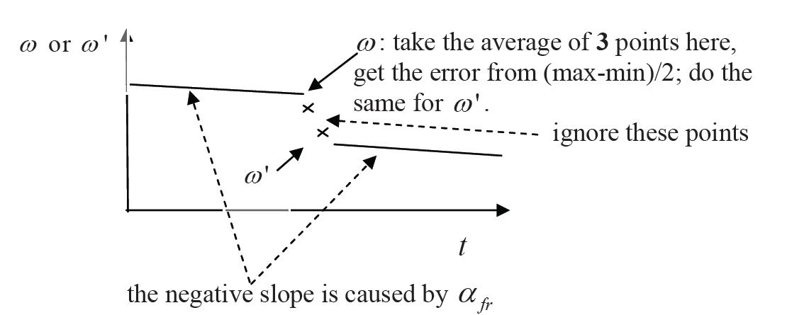
Note: The sign of the values for ω and ω′ (and the slope) may change depending on the direction the disk is spinning in. In general, you will expect to have a graph with a jump in the values of ω due to the dropped disk.
The higher line set of points corresponds to the initial angular velocity \( \omega \) and the lower line set of points corresponds to the final angular velocity \( \omegaʹ \). From the table of values record the angular velocity for 3 points on each side of the jump ω→ωʹ in your notebook (values close to the jump).
Calculate the average value of \( \omega \) and \( \omegaʹ \) and use half the difference between the maximum and minimum values of \( \omega \) and \( \omegaʹ \) as an estimate of the error in these two quantities.
Calculating \( I_{disk} \)
Next, calculate the moment of inertia of the dropped disk, \(I_{ disk} \). We assume that the disk is cylinder rotating about an axis through its center, so, with mass \( M\) and radius \(R\), use the formula: $$ I_{disk} = \frac{1}{2} MR^2 $$
Calculate the value of \( \Delta I_{ disk} \) taking in to account only the error in R : $$ \frac{\Delta I_{disk}}{I_{disk}} = 2 \frac{\Delta R}{R} $$
Calculating \( I' \)
The total moment of inertia \( Iʹ\) of the combined object (platform + dropped disk) is simply the sum of the two moments of inertia, $$ I' = I + I_{disk} $$
Record \( I' \) in your notebook. This value is only valid if the axis of rotation goes through both the center of the rotating table and the center of the dropped disk. That is, when you calculated \( I_{disk} \) you used an equation which was valid only if the axis of rotation went through its center) and the above equation is only complete if the disk is centered on the platform2.
Find the uncertainty in \( I′ \) by propagating the error of \( I \) and \(I_{disk}\): $$ \Delta I' = \sqrt{( ΔI )^2 + ( ΔI_{disk} )^2 } $$
Compare \(L\) and \(L′ \)
You are now ready to work out \(L\) and \(L′ \) from the defintion, found in equation (1).
You should also calculate the error in \( L\) and \(Lʹ \) taking into account the uncertainties in the moments of inertia and the measured angular velocities. Once we have done this we can see if \(L\) and \(L′\) are the same within experimental uncertainty: $$ \frac{\Delta L}{L} = \sqrt{(\frac{\Delta I}{I})^2 + (2\frac{\Delta \omega}{\omega})^2} $$
Answer the following questions in your lab notebook:
- Was angular momentum conserved in your experiment (within experimental error)? If not, what are possible reasons? $$ L \stackrel{?}{=} L' $$
- The value of \( I\) we used was found by measuring an angular acceleration \(\alpha\) when appying a torque \(\tau\). However, we neglected to consider the effect of friction, which would be a frictional torque \(\tau_{friction}\). How would having a significant \(\tau_{friction}\) affect our value for \(I\)? How would this corrected value of \(I\) affect the determination of whether \(L\) is conserved in this collision?
Hovering over these bubbles will make a footnote pop up. Gray footnotes are citations and links to outside references.
Blue footnotes are discussions of general physics material that would break up the flow of explanation to include directly. These can be important subtleties, advanced material, historical asides, hints for questions, etc.
Yellow footnotes are details about experimental procedure or analysis. These can be reminders about how to use equipment, explanations of how to get good results, or clarifications on details of frequent confusion.
Value is from NOAA for Latitude: 40.91597332879679, Longitude: -73.12491620370486, MSL Height: 41.0 Predicted gravity: 980269 +/- 2 milligals where a "gal" is a centimeter per second squared
A reasonable value is \(2200 \pm 200\) gram-centimeters-squared or \(2.2\times 10^{-4} \pm 0.2\times 10^{-4} \) kg-m2
If an object is rotating about an axis which is not through its center of mass, one can use the Parallel Axis Theorem to help find the new moment of inertai about that axis.