Measurement of e/m for Electrons

In this experiment you will measure \(e/m\), the ratio of charge \(e\) to mass \(m\) of the electron. This was first determined by J.J. Thomson in 1897 and was a key step in understanding the nature of the electron 1.
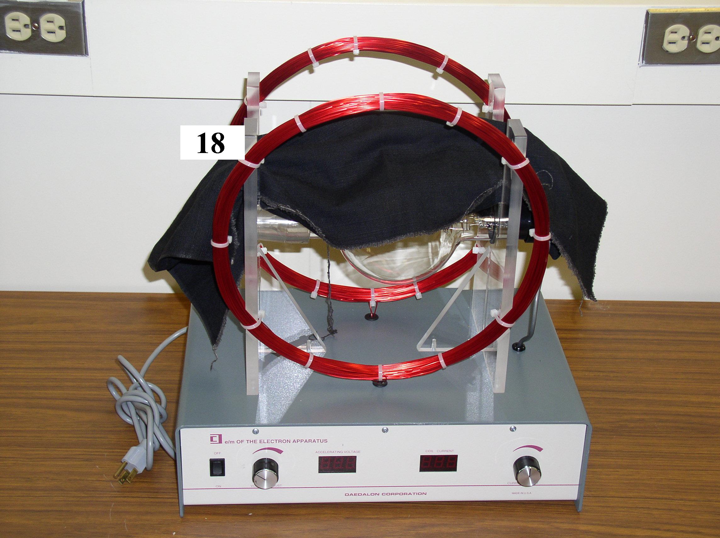
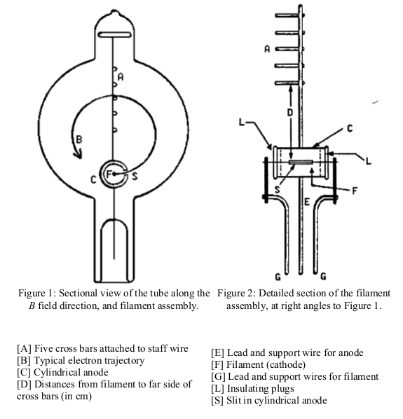
The set-up consists of a visible beam cathode ray tube 1 used to produce a beam of electrons of known energy. The tube contains an electron gun which emits, accelerates, and focuses electrons. For an electron of charge \(e\) and an accelerating voltage \(V\) the (non-relativistic) kinetic energy of the electrons is given by:
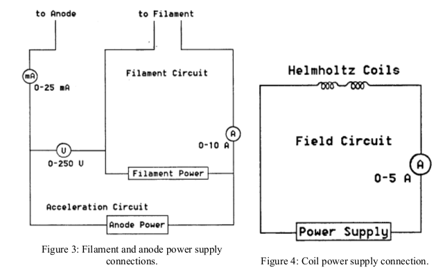
$$ K=\frac{1}{2}mv^{2}=eV $$The tube is supported at the center of a pair of large Helmholtz coils producing a uniform magnetic field \(B\) perpendicular to the velocity of the electrons. Thus, the electrons will be deflected to trace a circular path with a radius determined by \(e/m\), the accelerating voltage \(V\), and the magnetic field \(B\) (see equation 2). Helmholtz coils produce a very uniform magnetic field in the region half-way between the coils defined by:
$$ B=\frac{\mu_{0}NIR^{2}}{(R^{2}+x^{2})^{3/2}} $$
where \( \mu_{0}=4\pi\times10^{-7} \mathrm{Henry\,m^{-1}} \) is the magnetic permeability of free space, \( N = 130 \) is the number of turns on each coil, \(I\) the coil current, \(R\) the mean radius of the coils, and \(2x\) 2 the distance between coils.
Determine \(R\) and \(x\) (and their errors!) with a meter stick. Then, for a given coil current \(I\), vary the accelerating voltage V and read off the diameter, \(d\), of the electron orbit. This is done most accurately by tuning the voltage \(V\) such that the beam coincides with a centimeter or half centimeter mark in the ruler within the tube. Perform measurements for as many voltage settings as possible, then repeat the sequence for several different current settings.
The ratio e/m is given by:
$$ \frac{e}{m}=\frac{2V}{(Br)^{2}} $$For each \(I\), plot \(V\) versus \( B^{2}r^{2}\) (where, of course, \(r=d/2\)). You should obtain straight lines. Determine e/m from the slope and average over the different values obtained for different values of \(I\). Perform an error analysis estimating your uncertainties in all measured quantities. Compare your final result with the literature value and discuss possible deviations. Derive equations (2) and (3). Discuss how you would improve the precision of the \(e/m\) measurement.
The apparatus you will use is a Daedalon EP-20. The diagrams below are not specific to this model.


Hovering over these bubbles will make a footnote pop up. Gray footnotes are citations and links to outside references.
Blue footnotes are discussions of general physics material that would break up the flow of explanation to include directly. These can be important subtleties, advanced material, historical asides, hints for questions, etc.
Yellow footnotes are details about experimental procedure or analysis. These can be reminders about how to use equipment, explanations of how to get good results, troubleshooting tips, or clarifications on details of frequent confusion.
Fluorescence of low pressure He gas in the tube creates the blue-green glow.
Helmholtz coils are often made with \( x=R/2 \) which results in a simpler form of Eq. 2. What quantity is minimized at this condition? Why might this device have been made with \( x>R/2\)?
Chapter references are for "Modern Physics for Scientists and Engineers, 4th Edition" by Stephen Thornton and Andrew Rex, Cengage Publishing. Section 1.6