Scattering Angles and Differential Cross-Section

Much of what we know in nuclear and particle physics comes from the study of reactions, where incident particles (\(\gamma\), e,p, n, heavy nuclei) impinge on a target (also moving in collider experiments) and we detect the outgoing results. The rate of each processs can be summarized as an effective cross-section (\(\sigma\), with units of area) for that interaction 1.
The purpose of this laboratory is to show how certain characteristics of an object can be determined from the distribution of particles (or radiation) scattered from the object, the concept of the “differential cross section” \( \frac{d\sigma}{d\Omega}\). This describes how the outgoing directions of scattered particles are distributed in angle ( \( \Omega \) is the symbol for solid angle.)
In particular, we will use the scattering of a beam of laser light to indirectly measure the radius of several plexiglass cylinders. The method is similar in principle to that used in particle beam experiments to determine the size and shape of target nuclei. However, it is a two-dimensional analog; instead of solid angle, only circular angles \( \theta\) are used, and the differential cross section is \( \frac{d\sigma}{d\theta}\).

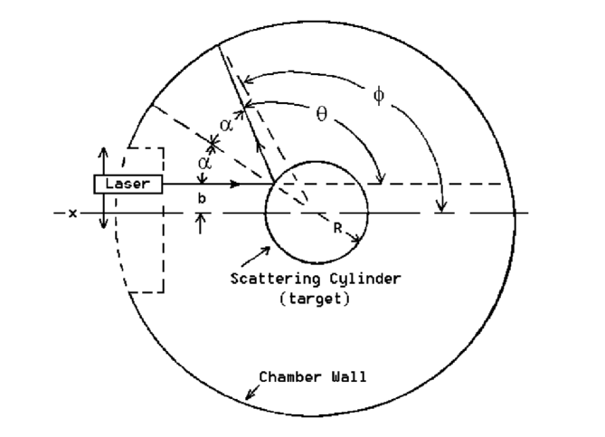
Imagine a well-collimated beam of light striking a polished circular cylinder as shown in Figure 1. \( R\) is the cylinder radius, and \( b\) is the “impact parameter,” i.e. the distance between the beam and the parallel line passing through the center of the target 1. After striking the target, the beam is reflected such that the angle of reflection \(\alpha\) equals the angle of incidence. From geometry, it follows that \( \sin\alpha = \frac{b}{R} \). Defining the total reflection angle \(\theta=\pi-2\alpha\), we see that \(\alpha=\frac{\pi-\theta}{2}\). Thus:
$$ \sin\alpha=\sin(\frac{\pi-\theta}{2})=\cos(\frac{\theta}{2}=\frac{b}{R}) $$ $$ b=R\cos(\frac{\theta}{2}) $$Suppose that \(b\) is changed by an infinitesimal amount \( \rightarrow b + db \). This will cause a corresponding change \(d\theta\) in the scattering angle, which can be found by differentiating Eq.(2):
$$ db=-\frac{R}{2}\sin(\frac{\theta}{2})d\theta $$If this experiment is performed \( dN \) times, while keeping the laser beam aligned so that the impact parameter is between \(b\) and \( b + db \), one will measure \(dN\) scattering events in the angular interval between \(\theta\) and \( \theta + d\theta \). Thus, the number of scattering events per unit angle is:
$$ \frac{dN}{d\theta}=\frac{R}{2}\sin(\frac{\theta}{2})\frac{dN}{db} $$where we used Eq.(3) and dropped the minus sign as we are interested only in the absolute values of the quantities concerned, i.e. the scattering rate. Here, \( \frac{dN}{db} \) can be regarded as the incident intensity or flux. The differential scattering cross section is defined as the ratio of the number of scattering events per unit angle to the incident flux:
$$ \frac{d\sigma}{d\theta}=\frac{dN/d\theta}{dN/db}=\frac{R}{2}\sin(\frac{\theta}{2})$$In a three-dimensional scattering experiment, flux is the number of incident particles per unit area (transverse to the beam.) Here, in a two-dimensional experiment, flux is particles per length. In a three-dimensional experiment, the cross section, \( \frac{d\sigma}{d\Omega} \) takes the place of the angle-dependent scattering cross-section \( \frac{d\sigma}{d\theta}=\frac{R}{2}\sin(\frac{\theta}{2}) \) , and has units of area. Here, in two dimensions, the cross-section has units of length.
However, there is an interesting wrinkle. In an actual scattering experiment, the target is not a reflector, but a container which admits the probe particles (e.g. laser light), allowing them to scatter from contents in the interior. When a scattered particle appears on the chamber wall, we do not know either the true impact parameter \(b\), or the “total angle of reflection” \( \theta ' \) (which depends on an unknown radius \(R'\) \(\leq R\) )) where the scattering occurred. What we do know and measure, is the “scattering angle” \(\phi \) shown on the figure, which is measured from the center of the target. The information from the experiment is then encoded in the differential cross-section \(\frac{d\sigma}{d\phi}\). This is a bit different from the previously defined \( \frac{d\sigma}{d\theta}\). It is \( \frac{d\sigma}{d\phi}\) that is measured in this experiment, because it is \( \phi \) that you actually measure. The difference between \(\theta\) and \(\phi\) is usually made small by designing apparatus with \( r>>R \) where r is the distance at which the scattering is measured, in this case the distance from the center of the target to the wall where the scattered light is observed. The condition \( r\gt\gt R \) is not quite the case here. A translation between the measured angle \( \phi \) and the geometric reflection angle \(\theta\) is needed. It will be discussed below.
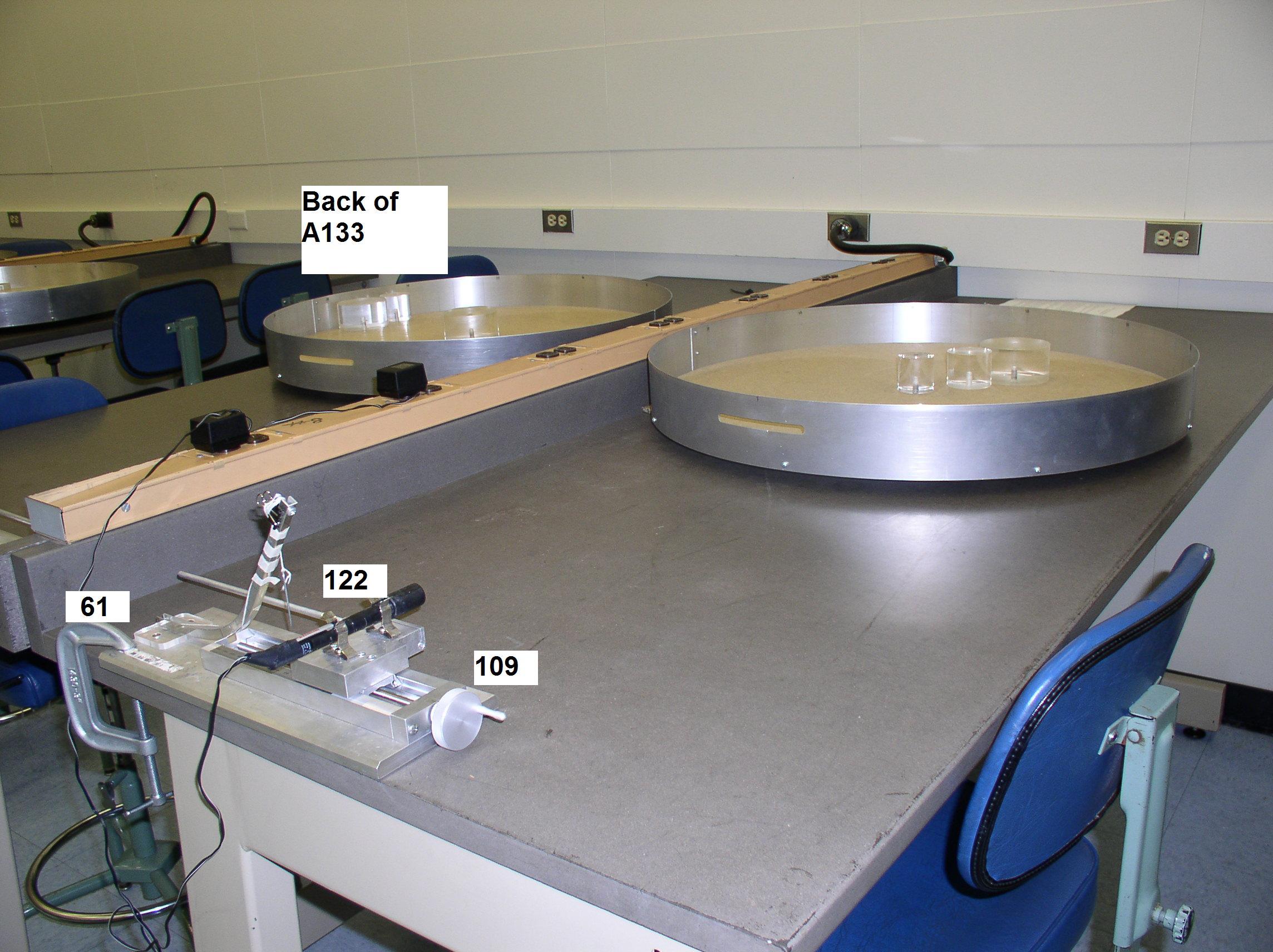
- Start by aligning the laser along and parallel to the diameter of the chamber. This is the case \( b=0 \). You will use the linear actuator to change \( b\) and identify into which angular "bin" the laser beam is reflected.
- As you change \(b\) you should perform four scattering measurements for each 0.1 cm step in \(b\) which corresponds to making a measurement approximately every quarter turn. The measurement consists of identifying which angular “bin” the scattering falls in: the chamber wall is marked in \( \Delta\phi=5^{\circ} \) increments. These are your bins. You should count the number of events \( \Delta N \) where the scattered laser spot ends up in each angular interval \( \Delta\phi \) of \(\phi\) as you vary \( b\).
- As you are measuring 4 times in each 0.1cm increment of \(b\), \( \frac{dN}{db}=\frac{4}{0.1\mathrm{cm}}=40 \,\mathrm{events\,.cm^{-1}} \). If you were to measure a different number of times for each turn you would modify \(\frac{dN}{db}\) accordingly. In an actual scattering experiment, the probe particle beam has randomly spaced particles, so that \(b\) is sampled randomly, but our procedure here in which \(b\) is continuously varied by you turning the handle is more efficient than doing thousands of measurements at random values of \(b\), a source of additional random noise.
- By dividing the the number of events \(\Delta N \) by the angular interval \( \Delta\phi \), we obtain the ratio \( \frac{\Delta N}{\Delta \phi} \), which is our approximation to \( \frac{dN}{d\phi}\). When \( \frac{dN}{d\phi}\) is divided by the flux \(\frac{dN}{db}\), you get the scattering cros-section \( \frac{d\sigma}{d\phi} \).
- Plot \( \frac{d\sigma}{d\phi} \) versus scattering angle \(\phi\). You should do this experiment three times, once for each of three different plexiglass cylinders.
We have a theory, \( \frac{d\sigma}{d\theta}=\frac{R}{2}\sin(\frac{\theta}{2}) \), derived geometrically from laws of optics. We know from the figure that \( \theta \) is close to, but a little less than, the actual measured scattering angle \( \phi \). You can also see that the difference between \( \theta \) and \(\phi\) should be smallest for back-scattering, \( \theta \approx \pi \), and largest for forward scattering, \( \theta \approx 0 \). You should derive the geometric relation \( r\sin(\phi-\theta)=R\sin(\alpha)=R\cos(\frac{\theta}{2}) \). It may help to recognize that each side of this equation equals the impact parameter \(b\). There is no simple solution of this relation that gives \(\theta\) in terms of \(\phi\) or vice-versa. So you can proceed “by iteration.”
- First, suppose that you can ignore the difference between \(\theta\) and \(\phi\) . Then theory says, if you plot \( \frac{d\sigma}{d\theta}\) versus \( \sin(\frac{\phi}{2}) \), it should give a straight line with slope equal to \(\frac{R}{2} \), modulo corrections to worry about in a minute. Provided your graph has a decent straight-line approximation, especially near back-scattering, you now have your first estimate of the cylinder radius \( R_{0}\approx R \).
- By some algebra and a Taylor expansion of the inverse sine function, you can obtain a formula for the first correction, \( \theta\approx\phi-\frac{R}{r}\cos(\frac{\phi}{2})\) . Note that this equation definitely works only when angles are in radians! This gives a “corrected” theory, $$ \frac{d\sigma}{d\phi}\approx\frac{R}{2}\sin(\frac{1}{2}(\phi-\frac{R_{0}}{r}\cos{\frac{\phi}{2}})) $$
- What this tells you is that now you can make another plot of \( \frac{d\sigma}{d\phi} \) versus the corrected quantity \( \sin(\frac{1}{2}(\phi-\frac{R_{0}}{r}\cos{\frac{\phi}{2}}))\). The slope (multiplied by 2) will give you a corrected radius, \( R_{1} \) . You are hoping for an improved straight line graph, from which you get an improved slope. If so, and if the corrected value \( R_{1} \) is not too far from the original value \(R_{0} \) , you are entitled to believe that your experiment confirms the theory, and that you have measured the radius of a plexiglass cylinder by a scattering experiment.
- You can in principle do further iterations, finding \(R_{3}\), etc. until convergence is obtained. This should not be necessary here.
- Estimate the errors of the radii \(R\) measured this way, and compare with the sizes of \(R\) that you measure directly with a ruler.
Hovering over these bubbles will make a footnote pop up. Gray footnotes are citations and links to outside references.
Blue footnotes are discussions of general physics material that would break up the flow of explanation to include directly. These can be important subtleties, advanced material, historical asides, hints for questions, etc.
Yellow footnotes are details about experimental procedure or analysis. These can be reminders about how to use equipment, explanations of how to get good results, troubleshooting tips, or clarifications on details of frequent confusion.
A non-zero impact parameter means that the projectile and target have an angular momentum about their combined center-of-mass. Consideration of L-waves is part of scattering theory.
Chapter references are for "Modern Physics for Scientists and Engineers, 4th Edition" by Stephen Thornton and Andrew Rex, Cengage Publishing. Scattering is discussed in Section 4.2 and 13.1