
The Michelson Interferometer
To better understand the interferometer used by Michelson and Morley, we use a simplified version of their instrument to measure the wavelength of the laser light source used 1. The second part of the experiment consists in measuring the index of refraction of air by counting fringe shifts in the interference pattern.
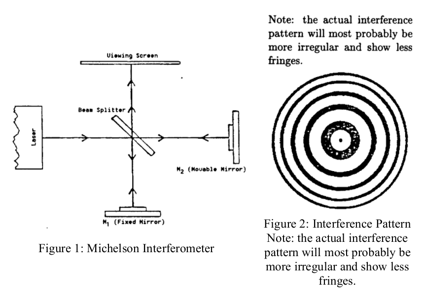
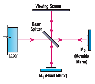
In the interferometer pictured below, the light from a (nearly) monochromatic source is split into two beams which recombine to form a visible pattern of areas of constructive and destructive interference; i.e. bright and dark fringes. When the effective length of one of the optical paths is changed by some means, then any given point on the interference pattern shifts from light to dark or vice-versa for each half-wavelength of path length change.
The experiment starts with careful alignment of the interferometer 1. BE VERY CAREFUL WITH THE EQUIPMENT AS IT IS DELICATE AND EXPENSIVE! Never touch the mirror surfaces or bump, or drop any part of the apparatus.
A brief summary of the procedure is as follows:
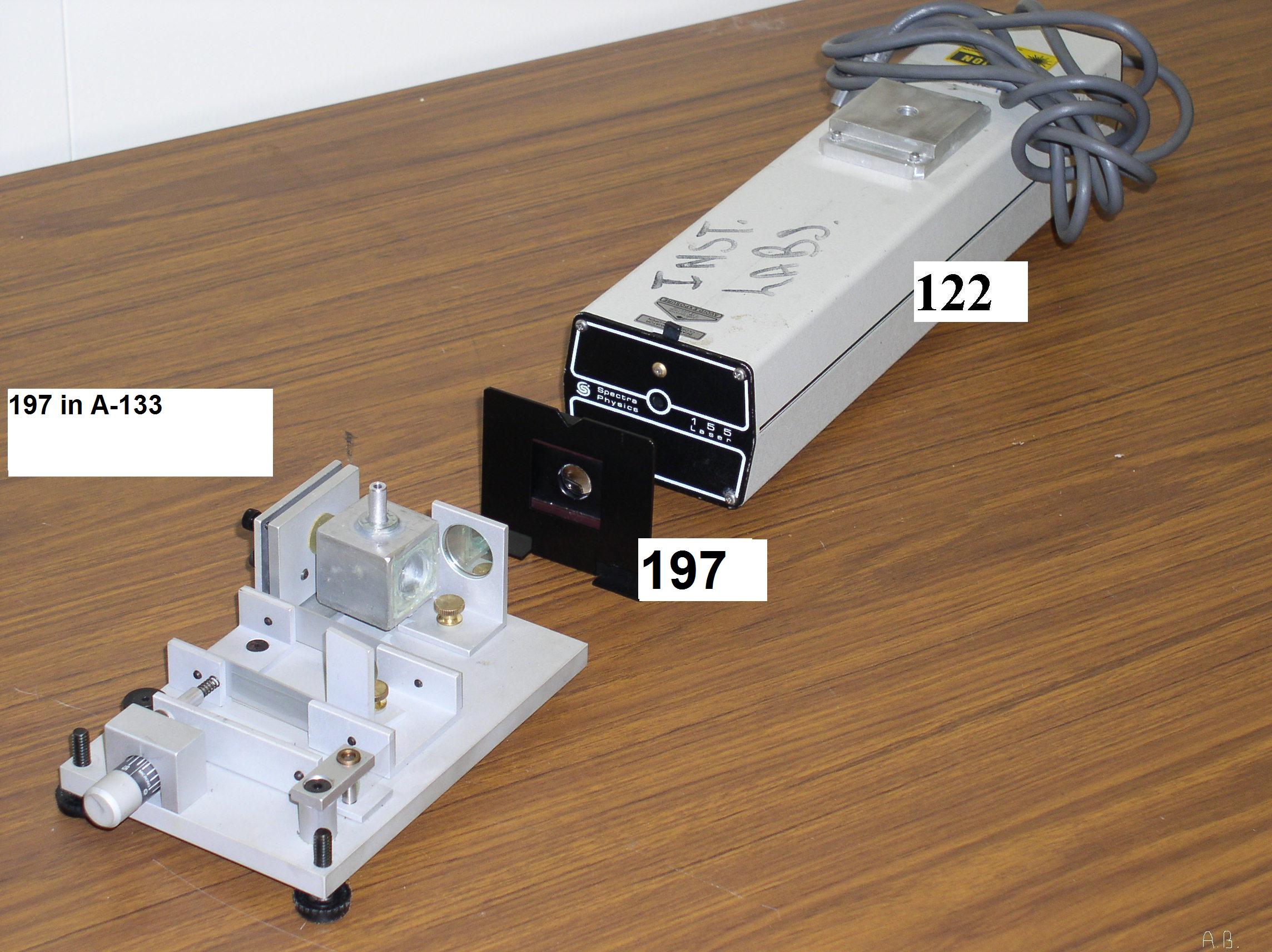
- Set the laser, interferometer and screen on your bench. Loosen the beam-splitter and swing it out of the laser path. Adjust the movable mirror, M2, so that the laser is reflected back toward the aperture of the laser.
- Swing the beam-splitter back into the laser beam and adjust to a rough 45 degree angle. Observe the two laser spots on the screen and carefully adjust the beam-splitter so that the spots overlap.
- Add the f=18cm lens to your system and adjust until you observe interference fringes on the screen.
Whenever the laser is turned on, NEVER look directly into the beam or its reflection!
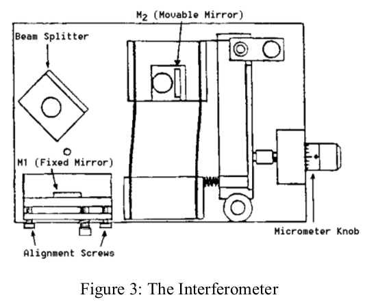
- Adjust micrometer knob so the lever arm is approximately parallel with the edge of the interferometer base. Then turn the micrometer knob one full turn counterclockwise. Continue turning counterclockwise until the zero on the knob is aligned with the index mark.
- Make a reference mark on the paper between two of the fringes.
- Rotate micrometer knob slowly counterclockwise. Count the fringes as they pass your reference mark. Continue until 25 to 40 fringes have passed your reference mark. As you finish your count, the fringes should be in the same position with respect to your reference mark as they were when your started the count.
- Record \(d_{m}\), the distance that the movable mirror moved toward the beam-splitter as you turned the micrometer knob. Each division on the micrometer knob corresponds to 1 μm of mirror movement.
- If the number of fringes that crossed your reference mark is \(m\) , the wavelength of the laser light is given by:
Derive the above equation and calculate λ and compare to the specified value of 632.8 nm.
In this part of the experiment you are aiming to carefully control the vacuum within the air cell that you should place in the beam path in between the fixed mirror and the beam splitter. You can achieve a slow control of pressure in one of two ways.
- Evacuate the air cell with the small hand-operated vacuum pump provided. When the best partial vacuum is attained, stop pumping and you will find that air slowly leaks back into the cell. As the cell pressure rises, the fringe pattern will shift.
- Alternatively you can very slowly use the pump and track the pressure as you increase the vacuum.
In either approach the key is to pay careful attention to the movement of fringes so you need to make sure not to have the pressure change too quickly while you measure. One partner should count the number of fringe shifts \(m\) as time goes by, and the other should record the pressure as a function of fringe-shift number. The relationship between the pressure change \( \Delta P\) and the number of fringe shifts \(m\) is given by (derive!):
$$ m=(n-1)\frac{2d}{\lambda}\frac{\Delta P}{P_{atm}} $$where \(\lambda\) is the light wavelength, \(n\)is the index of refraction of air at atmospheric pressure,\( d \) is the length of the air cell, \(P_{atm}\) is the current atmospheric pressure, and \( \Delta P = P_{cell}-P_{initial} \), where \( P_{cell} \) is the air pressure inside the cell at the \(m\)th fringe shift, and \( P_{initial} \) is the initial cell pressure. In the derivation of this expression one may assume that n depends on P as \( (n-1) \propto P \).
Plot \(m\) versus \( \Delta P \) on a graph and draw the best straight line through your data points. From the slope of this line and a knowledge of d, \( \lambda \) and \( P_{atm}\) determine \( n \). Estimate the experimental uncertainty on your measurements (by error propagation of various error sources) and compare to the literature value.
Hovering over these bubbles will make a footnote pop up. Gray footnotes are citations and links to outside references.
Blue footnotes are discussions of general physics material that would break up the flow of explanation to include directly. These can be important subtleties, advanced material, historical asides, hints for questions, etc.
Yellow footnotes are details about experimental procedure or analysis. These can be reminders about how to use equipment, explanations of how to get good results, troubleshooting tips, or clarifications on details of frequent confusion.
A more detailed guide can be found in the Pasco Manual for Michelson Interferometer
Chapter references are for "Modern Physics for Scientists and Engineers, 4th Edition" by Stephen Thornton and Andrew Rex, Cengage Publishing.
Michelson Interferometer Section 2.2