
Bragg Scattering
History
Even before Maxwell codified the equations for electromagnetic radiation, Fresnel and others established that light was a wave phenomena, subject to interference through superposition 1. When light is incident on a regular lattice, such as a diffraction grating, there are intensity maxima in the scattered light given by the familiar relation \(2d\sin\theta =m\lambda\) where \(\theta\) is the angle of the diffracted ray with respect to the normal to the grating and m is the order.
In the early 1900's it was not clear whether x-rays were e-m waves or particles. William and Lawrence Bragg, father and son, and others showed that x-rays were light with short wavelength through scattering experiments off crystals 2. This same method was used to establish the wave-particle duality of electrons and neutrons. Once the nature of the diffracted radiation was understood, the same experiment can be used to determine the structure and dimension of the scatterer, ie, the crystal 3.
Crystal structure
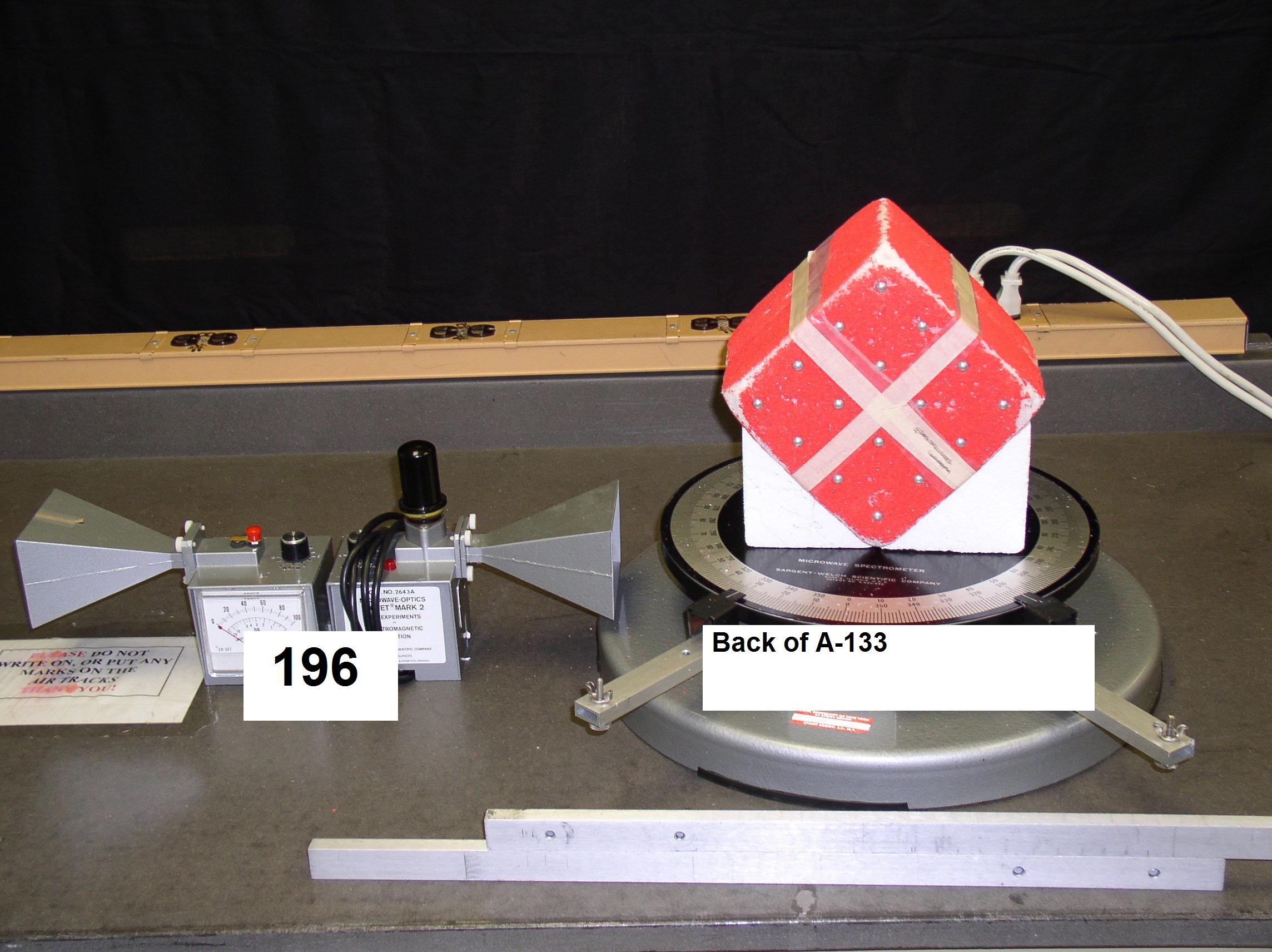
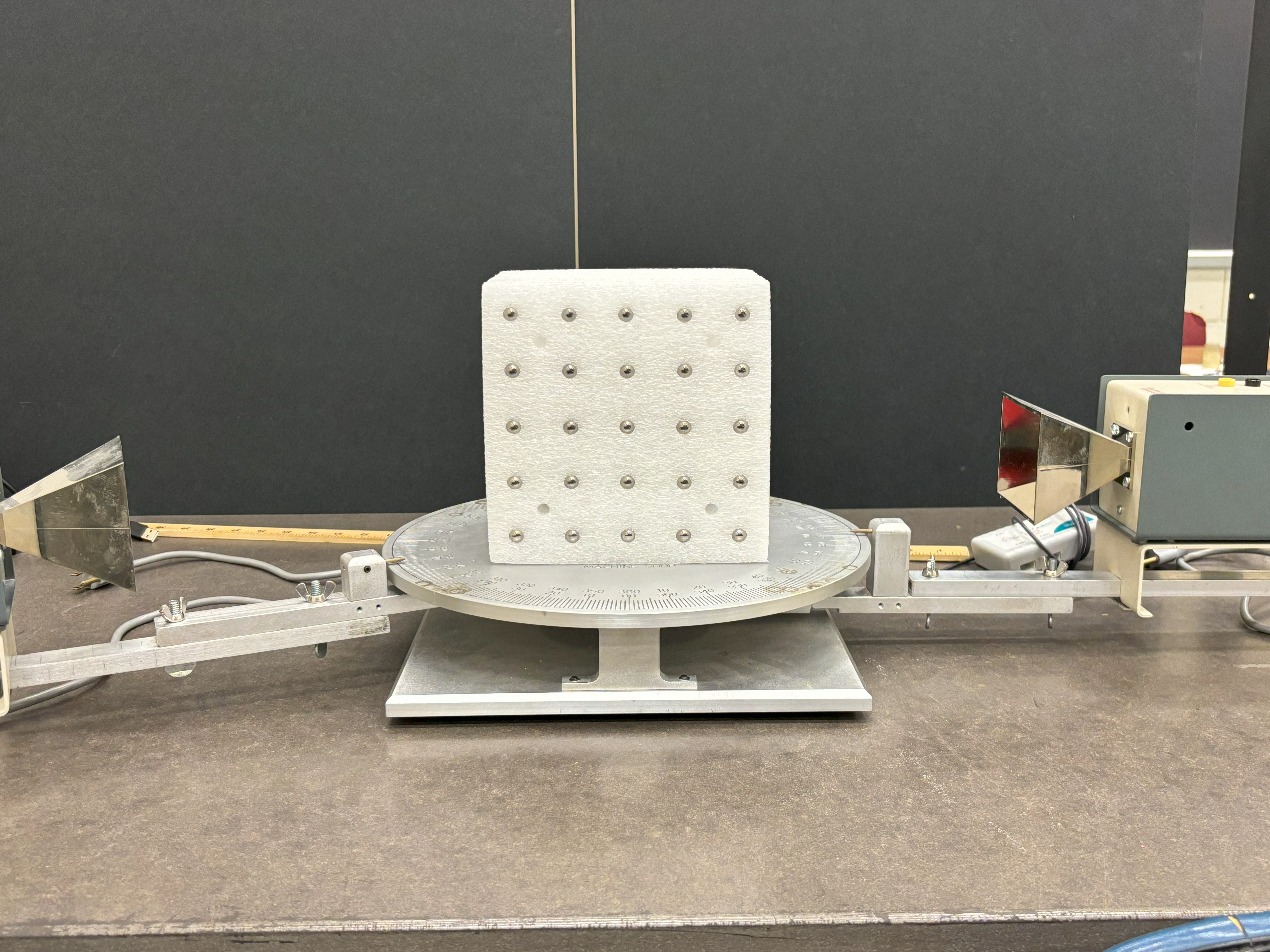
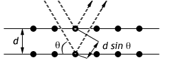
In this experiment, we will do "crytallography" via the scattering of microwaves from a “crystal” made up of ball bearings embedded in styrofoam. We will find diffraction maxima having the same form as those encountered in Bragg scattering of X-rays from crystal lattices. These obey the Bragg Law $$ 2d\sin\theta =n\lambda $$ This rule resembles the expression for diffraction of a grating except that \(\theta\) is defined with respect to the crystal surface and the order is "n".
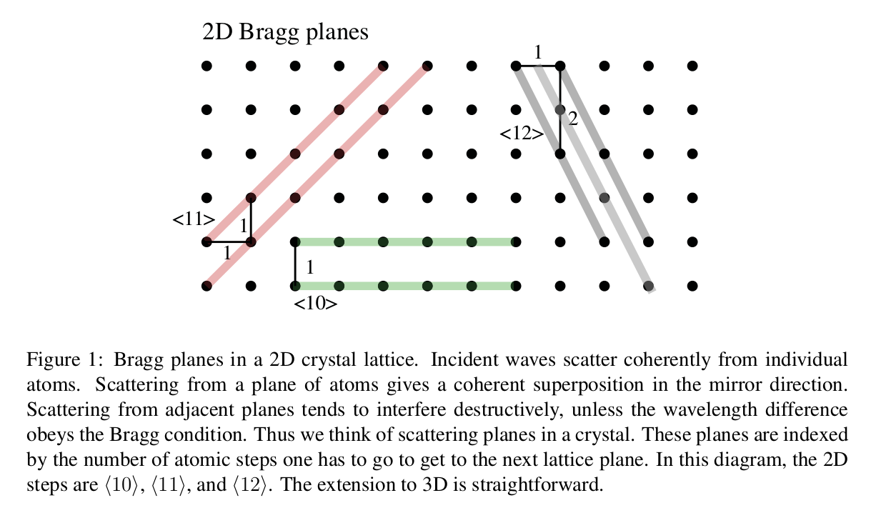
In the case when all atoms are in a simple cubic form with lattice constant \(a\) the distance between planes is $$ d=\frac{a}{\sqrt{l^{2}+m^{2}+n^{2}}} $$
where l,m,n are integers with no common divisor, called the Miller indices 4. The different scattering planes of a crystal are labeled by their Miller indices as {lmn}. Figure 1 shows a 2D version, but our “crystal” is 3D, as in Figure 2.

Microwaves
Since our crystal of foam and ball bearings has characteristic lengths of centimeters, we will use microwaves rather than x-rays. Microwaves are electromagnetic waves (light) with wavelengths in the range \(0.001\) to \(0.3\) m, shorter than radio waves and longer than infrared. Ordinary microwave ovens usually use \(2.45\) GHz, wavelength \(\lambda = 0.122 \) meters. Our microwave generators make somewhat shorter wavelengths (you will measure this). The source in an ordinary microwave oven is a “cavity magnetron.” In the lab, our source is a “klystron.” This uses resonant cavities, and an electron beam that amplifies the microwave energy in the cavities.
Here is a note on safety. Since the power density is so low, there is no danger from the microwaves themselves. Notice what happens to the receiver response when you put your hand between the two horn antennas.
Determine the wavelengh of the microwaves
-
Set up the microwave transmitter and receiver on a meter stick so that the horn antennas face each other. Turn on the transmitter and turn up the receiver sensitivity to about half-scale.
-
The transmitter/receiver system defines a low-grade optical cavity 1. When you have an odd number of half-waves between the two, \(\frac{n\lambda}{2}\) with n odd, you will see intensity minima in the receiver. Use this to determine the wavelength, by slowly moving the receiver straight out along the meter stick, measuring the distances of the successive intensity minima. Take readings over a wide range of distances to minimize the error.
Bragg Scattering
- Place the crystal on the platform 2 along the zero degree axis with the face oriented to look at the crystal plan you wish to test.
- Now place the transmitter and receiver on the arms of the goniometer. Observe the receiver response with transmitter AND receiver at various angles \(\theta\). Remember to move both arms! This photo shows only one of the elements rotated which is incorrect!
- Systematically look for Bragg scattering from the “crystal” planes, seeking in particular the {100}, {110}, {111}, planes from a a simple cubic lattice. In each case, test the Bragg formula \(2d\sin\theta =n\lambda\)
-
Determine the ball bearing spacing \(a\) from your scattering results and compare with directly measured values.
Hovering over these bubbles will make a footnote pop up. Gray footnotes are citations and links to outside references.
Blue footnotes are discussions of general physics material that would break up the flow of explanation to include directly. These can be important subtleties, advanced material, historical asides, hints for questions, etc.
Yellow footnotes are details about experimental procedure or analysis. These can be reminders about how to use equipment, explanations of how to get good results, troubleshooting tips, or clarifications on details of frequent confusion.
This method avoids the complicated problem of determining the exact dimensions of the cavity, which is a difficult E&M problem with complex boundary conditions.
The platform is often called a "goniometer", which means "angle measuring device".
Chapter references are for "Modern Physics for Scientists and Engineers, 4th Edition" by Stephen Thornton and Andrew Rex, Cengage Publishing. Waves and Particles, Chapter 1, Section 3.
Thornton and Rex. X-ray Scattering, Chapter 5, Section 1.
Thornton and Rex. Stucture of DNA, Figure 5.6
Thornton and Rex. X-ray Scattering, 5.1 and Solids, Section 10.3