Magnetic Force

In this lab, we will observe the force that a magnetic field exerts on a current-carrying wire.
By determining this force, we will deduce the strength of the applied magnetic field.Hoveroverthese!
- 1 Magnetic Force Apparatus
- 1 DC Power Supply (with current readout)
- 10g and 20g masses
- Record data in this Google sheets data table
The magnitude of the force on a wire in a magnetic field is:1
$$\vec{F}_B=I\vec{l}\times\vec{B}$$In this lab, we will be using a special case of this (for when the magnetic field and wire are orthogonal):
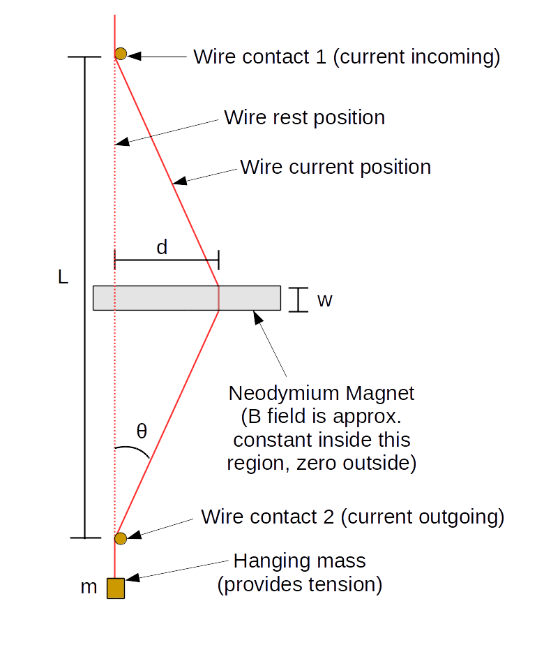
$$F_B=|\vec{F}_B|=IlB$$In this lab, you will be working with an apparatus represented by the following schematic:


Note that the magnets are located approximately halfway down the wire, such that \(L/2\) length of the wire is above and \(L/2\) is below. This makes the angle at the top equal to the angle at the bottom.
Since this angle is small in this experiment (so \(\sin(\theta)\simeq\tan(\theta)\)), we make the approximation that the length of the diagonal is fixed at \(L/2\) (rather than half the vertical), which allows us to derive a simple relationship between \(d\) and \(B\):
$$d=\frac{LF_B}{4mg}=\frac{LwB}{4mg}I\label{dformula}$$In fact, we will measure the horizontal position \(x\), where \(d=x-x_0\) (for \(x_0\) some rest position we don't care about), which obeys the equation:
$$x=\frac{LwB}{4mg}I+x_0$$Preliminary Measurements
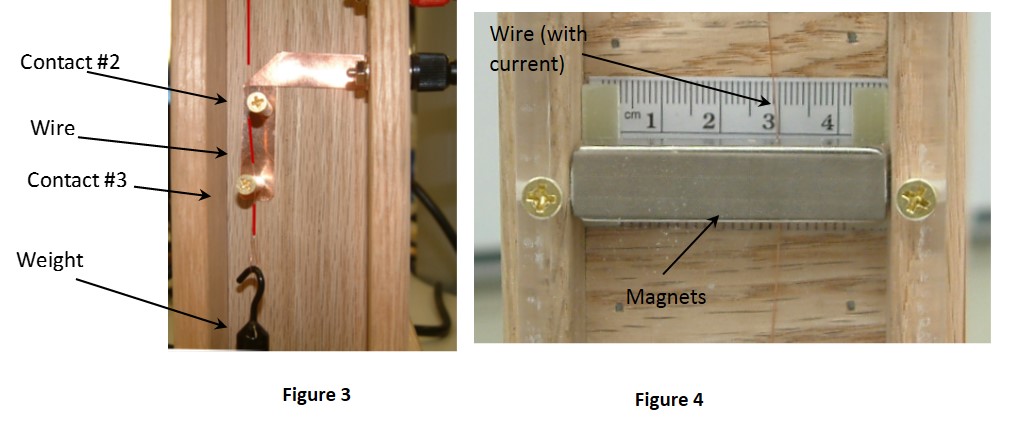
Using a meter stick, measure the distance \(L\) from the bottom contact (higher of the two at the bottom) to the top contact.
You may take \(w\) as given as 0.50" (the dimensions of the magnet are 0.50"x0.50"x2.00"), and convert that to SI units, or you can measure it yourself with a meter stick to the best of your ability.
Setting Up the Power Supply
We wish to use the power supply as a "current source". In this mode we can adjust the current and the power supply will use whatever voltage is needed to create that current.
First, set all knobs on your power supply all the way to the left.
Plug a wire directly from the red port of the power supply to the black port of the power supply. (Make a short circuit.)
Turn up the "coarse" current knob a little bit (a quarter-turn). Then, disconnect all wires.
Now, turn the voltage knob up until it reads somewhere around 5-6V. This is the "voltage limit".
Turn the current knob all the way down again, and then you're set up. (Leave the voltage knobs as they are for the rest of the experiment.)1
Now, plug in your power supply to your setup (red to red and black to black).
20g Mass Measurements
Hang a 20g mass to the bottom of your hanging wire. (Be gentle - the wires are very thin and fragile!)
Drape this wire through the contacts at the bottom, so it passes between them, touching both.
Do not loop it around either contact. If your wire is too long and your mass is resting on the bottom of the apparatus, tie a knot higher up in the wire to hang from (or consult your TA).
Now, take a measurement of your \(x\) position at zero current. This is your first data point.
Slowly increase the current to a maximum of 4.0A in increments of 0.66A, and record the current and position at each step.
Ensure as you do so that your wire does not have significant friction with either the front or back of the display.1
After you hit the end (at the maximum current), bring it back down to 0A again, also in 0.66A increments, and record the positions again.
10g Mass Measurements
Hang the other mass now, and do the exact same measurements as the previous part. Only two modifications are needed.
First, take increments of 0.5A instead of 0.66A. This will ensure you get enough data, due to the next instruction.
With the lighter mass, you will find that you reach the end of the position scale before you reach 4.0A. This is fine; just stop once you do so (and do not record any data with the wire in contact with the right-hand side of the apparatus), and go back down from there.
For each mass, make a plot of \(x\) vs. \(I\), and from the slope, calculate \(B\).2 Propagate all relevant uncertainties.
On the data table, state whether your results for the two masses agree with each other.
Your TA will ask you to discuss some of the following points (they will tell you which ones):
- Derivation of \eqref{dformula}:
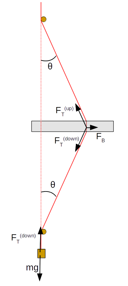
- Exact Result: Derive the exact version of \eqref{dformula}, starting from the force diagrams above. (You don't have to solve for \(d\), but you should find a relation that doesn't involve the angle \(\theta\).)
- Simplifying in Appropriate Limit: Make the approximation that \(\theta\) is small (equivalently that \(d\ll\frac{L}{2}\)), and show that equation \eqref{dformula} holds (to lowest order) in that limit.
- Small Angle Approximation:
- Estimating Impact: Compute the maximum angle \(\theta\) reached by your measurements. Compare \(\theta\), \(\sin(\theta)\), and \(\tan(\theta)\) at that angle. Is the small angle approximation justified, in the sense that these deviations are not as big as our uncertainties (as compared in a reasonable way)?2
- Qualitative: Pretend we knew the value for all variables in equation \eqref{dformula} (to a high degree of precision) except for \(d\) itself. Then, we could calculate a value for \(d_\text{small angle}\), the \(d\) according to our small angle approximation. How would we expect this to compare to our actual measured values for \(d\) (without the small angle approximation)? In other words, is the actual \(d\) value (based on the exact formula for \(d\)) larger or smaller than the "small-angle-approximation value"?
- Comparing Magnetic Field Strength: Look up the strength of the magnetic field of Earth: how does the magnet we have in this lab compare? How about to the strongest magnetic field ever made in a lab? How about to the magnet in an MRI machine? Which is it closest to (in scale)?3
- Reliability of Measurements: Which mass' B field measurement do you think is more reliable? (Consider in particular the sensitivity to outside forces.)
- Extending the Experiment: What level of precision in position would we need (order-of-magnitude) to measure the magnetic field of the earth? (Look up the magnetic field of the Earth, and see what \(d\) would be in such a case.) Is it plausible to have this level of precision, given reasonable instrumentation? Why/how?
Hovering over these bubbles will make a footnote pop up. Gray footnotes are citations and links to outside references.
Blue footnotes are discussions of general physics material that would break up the flow of explanation to include directly. These can be important subtleties, advanced material, historical asides, hints for questions, etc.
Yellow footnotes are details about experimental procedure or analysis. These can be reminders about how to use equipment, explanations of how to get good results, troubleshooting tips, or clarifications on details of frequent confusion.
For more information about magnetic forces on currents, see Katz Chapter 30.11 or Giancoli Ch. 27.3
What we just did is the following. The "voltage" settings set a maximum voltage the power supply will output, and the "current" settings set a maximum current. The power supply will always push either to the maximum current or the maximum voltage, whichever maximum it encounters first. Therefore, we first let it output some amount current (the specific amount wasn't important). The short-circuit ensured that plenty of current could go through (V=IR for very small R means very large I). After that, we unplugged it, which meant that no current could flow, so it went to the voltage maximum. This let us freely set an arbitrary voltage maximum. We then set it to a voltage such that it shouldn't obstruct us for the rest of the experiment. This will let us freely set the current, as we would like to.
The typical magnet strength is about 0.3T, although this does vary from experimental setup to setup.
If it seems to be getting "stuck," feel free to slightly "tweak" either the top or bottom to attempt to get it to "unstick."
Specifically: how does the relative differences in these quantities (e.g., \(\frac{\sin(\theta)-\theta}{\theta}\)) compare to than the relative uncertainties in our value for, say, \(B\)? Are these differences large enough that we shouldn't have made the small angle approximation?
More precisely stated: if you take \(\ln(B)\), which is closer to the strength of the magnets used in this lab: Earth or the strongest field in a lab?