Angular Momentum

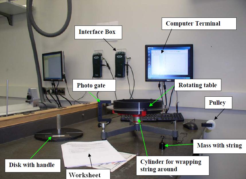
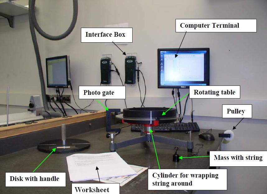
- Photogate setup
- Photogate
- Interface box ("LabPro")
- Computer
- Rotating Table
- Pulley setup (& table clamp)
- 200g mass (& string)
- Disk with handle
- Access to shared Vernier caliper or digital caliper
- Record data in this Google Sheets data table
This lab reviews many concepts from angular motion, with which you should be familiar. They are mostly analogous to linear motion, with a few subtleties.1
The "moment of inertia" (the analogue of "mass" for rotational motion) is \(m\langle r^2\rangle\), where \(\langle\ldots\rangle\) denotes the average. In particular, for a disk of mass \(M\) and radius \(R\), we find:
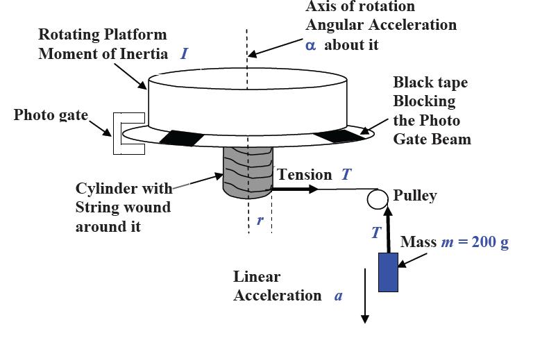
$$I_{disk}=\frac{1}{2}MR^2$$The analogue of force is called torque. In the first part of this lab, we will have two torques: a frictional torque (which will slow the wheel's spinning) and a "pulling torque" resulting from a hanging mass \(m\). We will set up our apparatus as follows:


The frictional torque will result in some angular acceleration \(\alpha_{fr}\) in the absence of hanging mass, which we will measure first. We will then add the hanging mass and determine the net angular acceleration, \(\alpha_{net}\).1
Based on the sum-of-torques equation on the platform and the sum-of-forces on the mass, we can find the equation for moment of inertia:
$$I=\frac{mr(g-r\alpha_{net})}{\alpha_{fr}+\alpha_{net}}\label{IPlat}$$Finally, we will spin this platform again (without hanging mass), drop a disk (of known \(I\)) on top of it, and determine whether we have conservation of angular momentum in this "collision" (of sorts).
Part I: Measuring Moment of Inertia of the Platform
Begin by opening "Angular Momentum" and connect your photogate as usual. Under "Data->User Parameters", enter the angle the platform turns per black-clear segment (in radians), \(\frac{\pi}{2}\simeq 1.571\).2
Place your photogate around the edge of the platform, so that it is blocked and unblocked as the platform spins and the black portions of the wheel slide underneath.
With the disk-with-handle off the top of the platform and the string and hanging mass not attached to the platform, start the platform spinning at some (relatively slow) speed.
Click "Collect" to make measurements with the photogate, and let it spin for somewhere in the range of 15-20s. You should observe a slow, linear decrease in angular velocity over time (with at least 10 measurements to base that on).1
Highlight your data2, and make a linear fit by clicking "Analyze->Linear Fit."3 Record the slope as \(\alpha_{fr}\).
Now, we want to measure \(\alpha_{net}\). Before we start setting that all up, let's get a measurement of \(r\), the radius of the spinning cylinder underneath the platform. If you use the Vernier calipers to do so; see the linked document for instructions on their use. Take an uncertainty of 0.5mm. Digital calipers or a small ruler is also fine, with similar or larger uncertainty.
Next, attach a string to the cylinder by putting a loop over the small metal peg4. Wind a turn or two of string around the cylinder. Now, drape the free end of the string over the pulley and hook on a 200g mass (record this value in your data sheet). Then, spin the platform to "wind up" the string around the cylinder, slowly lifting the mass until it reaches the pulley.
Hit "Collect," and when it says "Waiting for data...", release the mass. Once the mass hits the floor, stop collecting. Again, perform a linear fit to (the linear part of) your data, assuming you have at least ten data points based off of which to do so. Record this as \(\alpha_{net}\).
Part II: Validating Conservation of Momentum
Unhook the mass from your apparatus - you don't need it anymore.
Take the large disk with a handle (although we will neglect the handle in our calculations, and just pretend this is a solid disk). Record the mass of the disk (written on the disk; assume an uncertainty of 1g); then, measure the radius of the disk (and estimate uncertainty in that measurement).
Now, start your platform spinning, and hold the disk a short distance (~1cm) above the platform. Be sure the disk is centered!
Start collecting data with your photogate, and wait for 5 or so measurements. Then, drop the disk (and be prepared for a loud CLANK!) After a few more measurements (again, ~5 or so), stop recording.
You should observe three parts: a straight (slight-downward-sloped) line, a sharp drop (with data doing "something" in between), and then another (slight-downward-sloped) line. The first line is free-spinning before the drop, the second part is the "internal dynamics" of the drop, and the third part is the post-drop spin.
Take the last data point of the first part as your initial angular velocity and your first data point of the last part as your final angular velocity.
For your uncertainty in each of those angular velocities, take the length of time in between those measurements, and multiply by \(\alpha_{fr}\).2
Part I: Measuring Moment of Inertia of the Platform
Using formula \eqref{IPlat}, calculate the moment of inertia of the platform using your measurements.
For the uncertainty in the moment of inertia of the platform, you can take it to be the same relative uncertainty as your measurement of radius.3
Part II: Validating Conservation of Momentum
From the disk mass and radius, calculate the moment of inertia. Using that (and your measurements from part I), calculate the total (final) moment of inertia. Propagate uncertainties.
Then, using your moments of inertia and angular velocity measurements, calculate initial and final angular momenta, and propagate uncertainties. Finally, state whether (to within your uncertainty) angular momentum was conserved.
Your TA will ask you to discuss some of the following points (they will tell you which ones):
- Derivation of Moment of Inertia: Derive equation \eqref{IPlat} from the sum of torques and sum of forces equations.
- Systemic Error: Handle of the Disk: Note that our "disk" isn't really a disk. It consists of two parts: an outer disk, and an inner handle. Discuss the expected impact of the handle on the results. (First, determine how it impacts \(I\), assuming the total mass measurement is the same. Then, based on that, determine how that impacts our final angular momentum results.)
- Systemic Error: Off-Center Drop: Suppose your drop was slightly off-center. Discuss the expected impact of this on our results. (Hint: you can determine the impact on I using the parallel axis theorem.)3
- Friction in Part II: We measured \(\alpha_{fr}\) under the conditions in Part I. What about in Part II? Obviously, before the drop, it should be the same, but what about after the drop - should \(\alpha_{fr}\) change? (If it is not the same, is it bigger, smaller, or does it depend? If it depends, on what?) What about during the collision (as the disk lands)? Is any of this relevant to our experiment, and if so, how?
- Uncertainty Propagation for \(I\): By referring to section A.3.1 of the Error Analysis Guide and the general (one-variable) error formula contained therein, derive the "proper" formula for the uncertainty in \(I\) for part I (still assuming no uncertainty in \(\alpha\) or \(m\), but including the \(r\) dependence of the second term). Then, show that if we make the approximation \(r\alpha_{net}\ll g\), we get the result we used: that the relative errors in \(I\) and \(r\) are the same.
- Alternative Analysis Method: Suppose we wanted to use more hanging masses in part I, for more data. Show that we could include these by doing an \(\alpha_{net}\) vs. \(mr(g-r\alpha_{net})\) plot. First, show that if we were to plot those variables, we should get a linear relationship (with intercept). What would the slope be? What would the intercept be (physically)?4
Hovering over these bubbles will make a footnote pop up. Gray footnotes are citations and links to outside references.
Blue footnotes are discussions of general physics material that would break up the flow of explanation to include directly. These can be important subtleties, advanced material, historical asides, hints for questions, etc.
Yellow footnotes are details about experimental procedure or analysis. These can be reminders about how to use equipment, explanations of how to get good results, or clarifications on details of frequent confusion.
For an understanding of angular momentum, see Katz Chapter 12 & 13 or Giancoli Chapters 10 & 11.
See also: the Photogate Reference Manual.
See Katz Cha 13-2, example 13.5 or Giancoli Cha 10-7, example 10.13.
For our convenience, we define both of these quantities such that they are positive, even though they are in opposite directions. In other words, we are working with magnitudes in our calculations here.
Really, this is accounting for a systematic error - the friction force - with an uncertainty. We should just add something like this "natural loss" to our final angular momentum and see whether the losses match what we expect. But in the interest of simplicity, we just take this as our uncertainty.
The full error propagations are quite complicated and messy to do "correctly", so (in addition to neglecting uncertainties in \(\alpha\) and \(m\)), we've made a simplifying assumptions that \(r\alpha_{net}\ll g\). This means we can neglect the other factor of \(r\) in the second term in equation \eqref{IPlat}.
It's certainly strange to have dependence on \(\alpha_{net}\) in both our \(x\) and \(y\)-axes, and this could cause subtle technical issues involving correlations. Those are beyond what we usually tend to care about in this course, though (especially since we neglect the uncertainty in \(\alpha_{net}\) as it is). The advantage would be the ability to "easily" fit more data, without having to resorting to performing a "nonlinear fit" of \(alpha_{net}\) and \(m\) (which is, in general, a hard issue).
If the data collection times out too early, go to "Experiment->Data Collection," and increase the duration of the trials as necessary.
Highlight only the linear portion if there is a nonlinearity near the beginning or end for some reason. (If you do not have 10 data points in this region, repeat your trial.)
Or, you can click the "R=..." button at the top.
The peg sticks out of the cylinder up near the top. Careful, it can be sharp!