DC Circuits
In this lab, we will use measurements of voltage and current to determine resistance using Ohm's law, V=IR.
We will first measure the resistance of a single resistor. We will then measure how resistances combine in series and in parallel. Finally, we will look at the behavior of the resistance of a light bulb.Hoveroverthese!
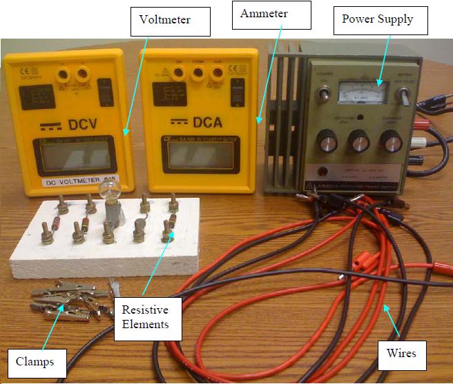
- 1 DC Power Supply
- 1 Voltmeter
- 1 Ammeter
- 1 Resistor Board
- 7 Banana Cables
- 8 Alligator Clips
- 1 Ohmmeter/Multimeter [per room]
- Record data in this Google Sheets data table

In this lab, we will be testing whether Ohm's law holds for both a resistor and a lightbulb:
$$V=IR$$We will also use this to analyze how resistors combine both in series and in parallel. In series, we expect resistances to add:
$$R_\text{series}=R_1+R_2$$In parallel, the inverses of the resistances add:
$$\frac{1}{R_{||}}=\frac{1}{R_1}+\frac{1}{R_2}$$Here, "series" means the same current flows through one resistor after the other (with a voltage drop across each one), whereas "parallel" means that the current splits between the two resistors (with the same voltage drop across all of them).1
Over the course of the lab, your TA will be going around measuring resistances of your resistors with a multimeter (or they may be provided ahead of time). Record those resistances on your data sheet (in part I; part II/III will copy automatically) when they do so.
Click here for advice on NOT burning out the fuse in your ammeter.
If you wire your circuits hastily, you may accidentally damage your equipment - in particular, you may burn out the fuse on the front of your ammeter. That's a fixable issue (talk to your TA), but it's still a waste of time and equipment, so here is best practice for wiring to avoid shorting out fuses in the ammeters:
- Before you wire up your circuit, turn off the power supply, voltmeter, and ammeter. Turn the voltage knobs on the power supply all the way down.
- Wire up your circuit. Double-check your wiring, to be sure. The most important thing is to make sure there is no route from the positive end to the negative end of the power supply which doesn't have a resistor (or voltmeter) along the way.
- Turn on the instruments. Set the voltmeter to its max setting, and the ammeter to its second-highest setting (as the 5A setting requires using the other port).
- Turn up the voltage on the power supply to something reasonable - say, middle position (on the "coarse" knob, if you have a three-knob power supply).
- Turn down the voltmeter/ammeter settings to the smallest number which is still larger than the given voltage/current. This ensures that you maximize your precision while not overloading your device.
- Finally, note that, as you take measurements, you should adjust the voltmeter/ammeter settings so that they are always the smallest number larger than the measured voltage/current. As the numbers change, your settings should, too.
The simpler power supplies only have one knob, which will be what you control your voltage with in this experiment. There are also three-knob power supplies, which are not much more complicated, but you have to know what knob does what.
Click here if you have a three-knob power supply.
First, turn the rightmost knob ("Current") all the way to maximum, and leave it like this for the rest of the experiment. The switch on the upper-right doesn't matter.
You'll be working with the other two knobs, which adjust voltage. The left knob is a "coarse" adjustment (to get you to the right ballpark), and the right knob is a "fine" adjustment (to tweak the voltage output). Use accordingly.
All voltages should be read off the digital voltmeter, not the analog display on the power supply.
Part I: Measuring the Resistance of a Single Resistor
First, choose a resistor to measure (R1 or R2), and record which one you chose on your data sheet. Then, wire the circuit up as shown below:2

Click here for step-by-step instructions for setting up your circuit for Part I.
Assuming you are starting with no wires connected:
- Begin by wiring a red wire from the red terminal on the power supply to the right (250mA max) terminal on the ammeter. (Note: if your current goes over 250mA during this experiment, you will need to change ports.)
- Connect the center (COM) terminal on the ammeter to the right-hand side of the resistor you're using (R1 or R2 on the board), using an alligator clip to attach to the resistor.
- Using a black wire, connect the left-hand side of the resistor you're using to the black terminal on the power supply (again using an alligator clip).
You should now have a loop that goes from your power supply, through your ammeter, through the resistor, and back to the power supply.
- Connect a red wire from the positive (red) terminal on the voltmeter to the right-hand side of the resistor using a new alligator clip.
- Connect a black wire from the negative (black) terminal on the voltmeter to the left-hand side of the resistor using another new alligator clip.
You should now have made a second loop that runs through your voltmeter instead of through the resistor. This completes the necessary wiring for this part.
Once everything is wired up, set your power supply to 5V or so. Measure voltage and current.
Slowly turn up your voltage to 10V in units of 1V (again, approximately). Measure voltage and current at each step.
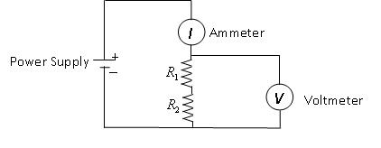
Part II: Resistors in Series
Wire the circuit up as shown below:

Click here for step-by-step instructions for setting up your circuit for Part II.
Assuming you are starting with no wires connected:
- Begin by wiring a red wire from the red terminal on the power supply to the right (250mA max) terminal on the ammeter.
- Connect the center (COM) terminal on the ammeter to the right-hand side of resistor R1, using an alligator clip to attach to the resistor.
- Using two alligator clips, connect the left-hand side of R1 to the right-hand side of R2. (Note: you may swap "left/right" as long as the resistors are still in series.The cartoon figure swaps left/right on R2).
- Using a black wire, connect the left-hand side of R2 to the black terminal on the power supply.
You should now have a loop that goes from your power supply, through your ammeter, through both resistors, and back to the power supply.
- Connect a red wire from the positive (red) terminal on the voltmeter to the right-hand side of R1 using a new alligator clip.
- Connect a black wire from the negative (black) terminal on the voltmeter to the left-hand side of R2 using another new alligator clip.
You should now have made a second loop that runs through your voltmeter instead of through the resistors. This completes the necessary wiring for this part.
Set your voltage to something reasonable (between 5V and 10V) and measure voltage and current.
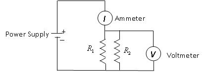
Part III: Resistors in Parallel
Wire the circuit up as shown below:

Click here for step-by-step instructions for setting up your circuit for Part III.
Assuming you are starting with no wires connected:
- Begin by wiring a red wire from the red terminal on the power supply to the right (250mA max) terminal on the ammeter.
- Connect the center (COM) terminal on the ammeter to the right-hand side of resistor R1, using an alligator clip to attach to the resistor.
- Using a black wire, connect the left-hand side of R1 to the black terminal on the power supply (again using an alligator clip).
You should now have a loop that goes from your power supply, through your ammeter, through the resistor R1, and back to the power supply.
- Connect the right-hand side of resistor R1 to the right-hand side of R2.
- Use a black wire to connect the left-hand side of R1 to the left-hand side of R2.
You should now have a second loop that goes through R2 instead of R1.
- Connect a red wire from the positive (red) terminal on the voltmeter to the right-hand side of either resistor using a new alligator clip.
- Connect a black wire from the negative (black) terminal on the voltmeter to the left-hand side of either resistor using another new alligator clip.
You should now have made a third loop that runs through your voltmeter instead of through either resistor. This completes the necessary wiring.
Set your voltage to something reasonable (between 5V and 10V) and measure voltage and current.
Part I
For the resistor you chose, make a plot of voltage vs. current. Determine the resistance based on this plot.
Answer the question on the data sheet about whether your result agreed with expectation.
Part II
Using the voltage and current you measured, calculate the resistance of the resistors in series. Propagate uncertainty.
Using the resistances your TA measured, calculate what the resistance should be. Propagate uncertainty.
Answer the question on the data sheet about whether your result agreed with expectation.
Part III
Using the voltage and current you measured, calculate the resistance of the resistors in parallel. Propagate uncertainty.
Using the resistances your TA measured, calculate what the resistance should be. Propagate uncertainty. (The data sheet will help you by breaking this calculation into steps.)
Answer the question on the data sheet about whether your result agreed with expectation.
Your TA will ask you to answer some of the following questions (they will tell you which ones to answer):
Experimental Questions:
- We typically make an assumption of an "ideal ammeter" with zero resistance (so it doesn't impede current). If our ammeter was (slightly) non-ideal, and in fact had some small resistance (say, a few ohms), would this be a concern for our resistance measurements? If so, how would it impact our results?
- We typically make an assumption of an "ideal voltmeter" with infinite resistance (so no current flows through it). If our voltmeter was (slightly) non-ideal, and in fact had some finite (but still very large) resistance (say, a megaohm), would this be a concern for our resistance measurements? If so, how would it impact our results?
- Hypothetically, suppose our resistance in part I was 200 ohms. Quantitatively calculate the impact of a 1 Ohm ammeter resistance and a 1 megaohm voltmeter resistance (rather than ideal circumstances). Based on the uncertainties in our experiment, are these systemic errors likely to be relevant?
Theoretical Questions:
- Recall that the power (energy per unit time) deposited into a resistor is \(P=IV\). What happens to this energy that is deposited?
- In general, resistor's resistance depends (slightly) on the temperature of the resistor, with the relationship depending on the details of the material. Do you expect the temperature of a resistor to increase or decrease as you run more current through it? Based on this relationship and your results from Part IV, how does the light bulb's resistance depend on temperature?
For Further Thought:
- In the circuitry, we advised using new alligator clips for each connection (in particular, when you connect the voltmeter). This helps to reduce a problem known as contact resistance: there is some resistance in the connection between the alligator clips and the resistors. Why would this help? (Hint: draw out the circuit diagram in both places, with this "contact resistance" in the appropriate place. In some places, the resistance is problematic; in other places, it is not.)31
Hovering over these bubbles will make a footnote pop up. Gray footnotes are citations and links to outside references.
Blue footnotes are discussions of general physics material that would break up the flow of explanation to include directly. These can be important subtleties, advanced material, historical asides, hints for questions, etc.
Yellow footnotes are details about experimental procedure or analysis. These can be reminders about how to use equipment, explanations of how to get good results, troubleshooting tips, or clarifications on details of frequent confusion.
For more information about Ohm's Law, see KJF Ch. 22.5. For more description of circuitry in general, see KJF Ch. 23.1-23.4.
Credit for the more realistic diagrams in this manual goes to past student Marina Niazi.
You also might try reading about a four-point resistance measurement, which is done for exactly this reason.
Realistically, this isn't within our precision to measure unless there is a lot of contact resistance (in which case Part III is still problematic, even with this resolution), but the principle stands.