
Centripetal Force
In this lab, we will study verify the equation for centripetal force, \(F_C=\frac{mv^2}{r}\).
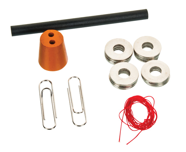
- 1 String
- 1 Stopper
- 1 Tube
- 16 Washers
- 1 Cord Clamp
- 1 Paper Clip
- 1 Stopwatch (your phone or Google will do)
- Record data in this Google Sheets data table
Recall that an object moving in a circle is undergoing an acceleration, because its velocity is changing (even if the speed is not). If the mass of the object is \(m\), the radius of the circle it travels in is \(r\), and the speed it travels at is \(v\), then the basic formula for the centripetal force on the object is:
$$F_C=\frac{mv^2}{r}$$Note that this is the net force on the object, and is always inwardly directed.11
In this experiment, it is convenient to write this a little differently. We define the angular velocity \(\omega\) as the rate of change of angle, which can be written as (note \(T\) denotes the period of the rotation):
$$\omega=\frac{v}{r}=\frac{2\pi}{T}\label{omega}$$Hence, we can equivalently write our centripetal force equation as:
$$F_C=m\omega^2r\label{cfomeg}$$It is also somewhat convenient to define the centripetal acceleration:
$$a_C=\frac{F_C}{m}=\frac{v^2}{r}=\omega^2r$$Now, to our particular experiment. Our setup consists of a stopper of mass \(m\) on the end of a string connected via a string through a tube to a bunch of washers of total mass \(M\). We hold the tube and spin the stopper in a horizontal circle, keeping the washers at a fixed height. The gravitational force of the washers will provide the inwards force on the stopper.
In practice, this looks like the following:
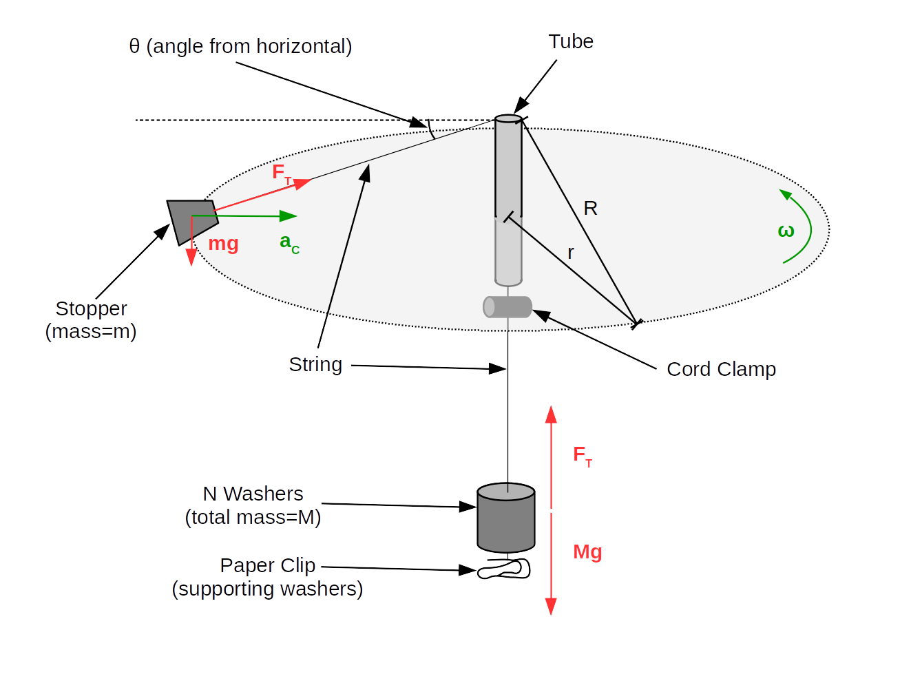
This is, unfortunately, not quite as simple as an "ideal" centripetal force setup, because we need to think about the gravitational effect on the stopper. (Fortunately, things will still end up working out nicely.)
Consider first the forces on the washers at the bottom of the string. There is gravity, \(Mg\), downwards, and tension, \(F_T\), upwards. Since the washers aren't moving, the net force must be zero, and hence the two forces must be balanced, yielding (in magnitude):
$$F_T=Mg$$Now, the more complicated part: the forces on the stopper. Here, we have two components: the virtical component, and the horizontal component.2
The vertical component has two forces to consider: tension, with a vertical component of \(F_T\sin(\theta)\) upwards, and gravity, with a vertical component of \(mg\) downwards. Since the stopper remains at fixed height, these balance out, and so \(mg=F_T\sin(\theta)\), although we won't actually use this relation.
For the horizontal component, the only factor that enters is the horizontal component of tension, \(F_T\cos(\theta)\). We know that the net inwards force is the centripetal force, so we find:
$$F_T\cos(\theta)=m\omega^2 r\label{ctheta}$$Now: let's discuss what we're actually measuring in this lab. Clearly, we can measure the period \(T\), which determines \(\omega\) according do equation \eqref{omega}. We can weight the stopper and the washers, which determines \(m\) and \(F_T\). But we don't have a nice, easy way to measure \(\cos(\theta)\) or \(r\) (since both of those are only determined when we swing).
However, we can measure \(R\), the length of string outside the tube.1 Note that the relationship between the radius of orbit \(r\) and the length of string above the top of the tube \(R\) is \(r=R\cos(\theta)\). By plugging this in to \eqref{ctheta} and cancelling the \(\cos(\theta)\), we find the relation we will actually be (directly) verifying in this lab, which looks almost identical to \eqref{cfomeg} (despite a slightly different meaning):
$$F_T=m\omega^2 R$$Part I: Preliminary Measurements and Setup
Begin2 by measuring two masses: the mass of the stopper, \(m\), and the mass of all 16 washers (combined), and note associated uncertainties.3
Now, make sure the string is fed through the tube with one end tied around the stopper and the other end tied around the paper clip, with the cord clamp on the string somewhere in between the tube and the paperclip.
Set the cord clamp so that when it is about 1cm below the bottom of the tube, your "radius," \(R\),3 is about 20cm. (No need to be precise here.) Put a few (say, 5) washers on the bottom of the string.
Before we actually take data, let's do a "test swing." Be careful that others are not near enough to you to get hit when you do this.
Hold the tube, and start spinning the stopper around over your head in a steady horizontal circle. Spin it fast enough so that the clamp goes up to the bottom of the tube.
Now: slow down your rate of spinning. You ultimately want the clamp to steadily maintain its position without putting any pressure on the bottom of the tube.
Once you feel you are at such a speed, pull down on the cord below to make the clamp be approximately 1cm below the bottom of the tube, then release it. Adjust your rate of spinning until you find that it stays there steadily (if it goes down, speed up spinning; if it goes up to the bottom of the tube, slow down your spinning further.)
Be sure you do not touch the string as you spin, only the tube. You should make sure that you neither hit your hand with the string at the top of the tube nor hold the string with the bottom as you spin. Also, ideally, you don't want the masses to swing too much (but again, don't hold them, we want them to hang freely).
Once you have all that down,4 you need to time how long ten rotations take, five times. This will allow you to determine the uncertainty in measuring \(10T\).
Make sure you are spinning steadily, and have your partner start the timer. Time out ten rotations (start counting at "zero" when you start the timer, so that you count "one" after one rotation). Record that time; then, repeat this measurement four more times.
Part II: Determining Dependence of Angular Velocity \(\omega\) on Tension Force \(F_T\)
First, we'll take a measurement of radius \(R\). If you thought that your earlier spinning was inconveniently fast or slow for your tastes, feel free to adjust your radius to something more convenient (although keep in mind that the centripetal force will vary, and that will change your speed).
Now, once you have decided on your radius, place your apparatus at rest on the table. Adjust the string until the clamp is ~1cm below the bottom acrylic tube.5 Measure the distance from the place where the string exits the tube to the center of mass of the stopper (which you should estimate the location of) as \(R\).
You may take your uncertainty in \(R\) to be 1cm. This seemingly-high uncertainty results from a combination of random errors but is dominated by the uncertainty in your ability to hold the clamp a steady 1cm below the tube as you swing.
Now, put \(N=3\) washers on the bottom of the string, and begin to swing the stopper, as you did your test swing before: keep the clamp ~1cm below the bottom of the tube as you do so.
Have your partner cue up the stopwatch, and measure the time it takes the mass to complete ten revolutions. When counting, you should start at "zero", so when you press start, say "zero," then "one, two..." as it finishes the first revolution, the second, up to the tenth.
Leaving the radius fixed, increase the number of washers to six. Again, calculate how long it takes to complete ten revolutions.
Repeat for nine, twelve, and sixteen washers. (Feel free to tweak these numbers if you need to for any reason - the exact numbers aren't important, just that you get an adequate range of centripetal forces.)
Part III: Determining Dependence of Angular Velocity \(\omega\) on Radius \(R\)
In this part, you will be doing the exact same measurements, just varying radius instead of number of washers.
Set the number of washers to five (or something else; it's not important). Set the radius to something small (~20cm) and measure the radius as before.
Again, measure the time it takes to complete ten swings for this radius.
Increase the radius to ~30cm. Measure it again, then swing and time ten periods for this new radius. Repeat for ~40cm, ~50cm, and ~60cm radii. (Or adjust those numbers - again, just get an adequate range of values.)
Part I: Preliminary Measurements
Divide the mass of all 16 washers combined by 16 to get the mass of a single washer. Propagate uncertainty.
Determine the average time ten revolutions took, and the uncertainty in a single measurement (not the average!). This will be your uncertainty in 10T for future parts.
Part II: Determining Dependence of Angular Velocity \(\omega\) on Centripetal Force \(F_C\)
For each trial, from your value of \(N\) and your mass of a single washer, determine first the total hanging mass, then the tension force. Propagate uncertainty.
For each trial, from your measurement of ten periods, calculate one period (and propagate uncertainty). From this, calculate frequency \(f=\frac{1}{T}\), angular velocity \(\omega\), and finally \(\omega^2\).
Make a plot of \(F_C\) vs. \(\omega^2\), with error bars. Take note of the slope, including its units.
Consider: what mathematical expression (in terms of quantities we measured) do we expect the slope to be?2 Calculate this expected slope (and propagate uncertainty), and compare the expected slope (from this calculation) to our measured slope (from the plot).
Part III: Determining Dependence of Angular Velocity \(\omega\) on Radius \(R\)
From your value of \(N\) and your mass of a single washer, determine first the total hanging mass, then the tension force. Propagate uncertainty.
For each trial, calculate \(\frac{1}{R}\) and propagate uncertainties. From your measurement of ten periods, calculate one period; from that, calculate frequency \(f=\frac{1}{T}\), angular velocity \(\omega\), and finally \(\omega^2\). Propagate uncertainties all the way through.6
Make a plot of \(\omega^2\) vs. \(\frac{1}{R}\), with error bars. Take note of the slope, including its units.
Consider: what mathematical expression (in terms of quantities we measured) do we expect the slope to be? Calculate this expected slope (and propagate uncertainty), and compare the expected slope (from this calculation) to our measured slope (from the plot).
Your TA will ask you to answer some of the following questions (they will tell you which ones to answer):
Experimental questions:
- We ignored the mass of the cord clamp and paper clip in our measurements. What would be the impact of this on our plot of \(F_C\) vs. \(\omega^2\)? On our plot of \(\omega^2\) vs. \(\frac{1}{R}\)?
- Suppose we could easily vary the mass of the stopper, and performed measurements of period at varying masses of the stopper, but constant number of washers and radius. What plot could we make that would have a linear slope in this case? What would be the expected slope of said plot?
Theoretical questions:
- If the string broke and the mass flew off, what trajectory would it follow? Describe in all three dimensions.
- Which of the following accurately describes the velocity with which the mass moves: \(v=r\omega\), or \(v=R\omega\)? Why?
- Consider the angle of the string below the horizontal, \(\theta\). How does this vary (if at all) as we vary the number of washers at constant radius in part II? As we vary the radius at constant number of washers in part III? What if we varied the mass of the stopper, but kept the same number of washers and radius?
- No matter how fast you swing the mass, the angle that the mass was swinging below the horizontal would never reach zero degrees (i.e., it would never swing perfectly in the horizontal plane). Why?
For further thought:
- Suppose we had measured velocity (say, with a radar gun) instead of period. How would this experiment be different? Could we draw similar conclusions? Why(/how) or why not?
Hovering over these bubbles will make a footnote pop up. Gray footnotes are citations and links to outside references.
Blue footnotes are discussions of general physics material that would break up the flow of explanation to include directly. These can be important subtleties, advanced material, historical asides, hints for questions, etc.
Yellow footnotes are details about experimental procedure or analysis. These can be reminders about how to use equipment, explanations of how to get good results, or clarifications on details of frequent confusion.
For more about circular motion and centripetal forces, see KJF Ch. 3.8 and 6.1-6.3.
You may find the Guide to Making and Using Plots helpful here, in particular the section "Understanding and Extracting Information from Fits"
For an object moving at a non-constant speed in a circle, that formula still holds for the component of force perpendicular to motion, but there is also a component of force parallel to motion to change the speed.
Slightly more accurately, we work with three components: a vertical component, a radial component, and a tangent (parallel to velocity) component. But there are no forces in the tangent direction (we aren't varying speed), so there's no reason to discuss it.
For convenience, we'll say "radius" to refer to \(R\), even though it's not really the radius (since \(r\) is actually the radius of orbit).
We can fix the length above the tube by fixing the length below the tube. This is where the "cord clamp" comes into play: by spinning with it located some fixed, known length below the bottom of the tube, we can also have a fixed, known length \(R\) above the top of the tube.
Depending on scale availability, it may be easier to do this later during the class; just be sure to get these measurements at some point.
Take your uncertainty in these mass readings to be given by the last decimal place the scale outputs (e.g., if it reads 16.46g, then you have as your uncertainty 0.01g).
So, to reiterate, make sure all of the following are true:
- The clamp remains steadily ~1cm below the bottom of the tube. Under no conditions should it ever touch the bottom of the tube during the time you are measuring.
- Your hand should only touch the tube, and no other part of the apparatus during the experiment (in particular, not touching the string) while measurements are taken.
- The stopper is swinging approximately in a horizontal plane.
- The hanging washers should not be swinging (much).
You may want to estimate by eye, because this is how you'll be estimating when you swing, and the important thing here is that the distance is the same when you measure \(r\) as when you swing, not that it's exactly 1cm.
Keep in mind that many (although not all!) of your calculations from part II can be copy-pasted into part III. That's a handy trick to know!